Ford 351 Cleveland Engines: Lubrication
When Ford was developing its 335 Cleveland engine family, the objective was to produce a large engine family with displacements ranging from 335 to beyond 400 ci as a companion to the larger 385-series 429/460-ci big-block engines.
Although the Cleveland has been conceived to consolidate engine families/displacements and lower manufacturingcosts, it was also a high-performance V-8 with its beefy bottom end, poly-angle valves, wedge chambers, huge ports, and dry-manifold induction system. To lower manufacturing costs, Ford had to reduce the number of machining and manufacturing steps, one of which resulted in fewer oil galleys. Although this really hasn’t had an adverse effect on street engines, it has plagued racers and hardcore performance buffs.

This Tech Tip is From the Full Book, FORD 351 CLEVELAND ENGINES. For a comprehensive guide on this entire subject you can visit this link:
LEARN MORE ABOUT THIS BOOK HERE
SHARE THIS ARTICLE: Please feel free to share this post on Facebook Groups or Forums/Blogs you read. You can use the social sharing buttons to the left, or copy and paste the website link: https://www.cartechbooks.com/blogs/techtips/351-cleveland-lubrication
The 335-series oiling system is different from the 289/302/351W small-block in that there’s one less oil galley, resulting in two galleys along the lifter bores. Oil is drawn to the pump from a front or mid-sump pan, then passed to a main horizontal oil galley across the front of the block where it leads to both cam bearings and main bearing journals, then up to the lifter galleys.

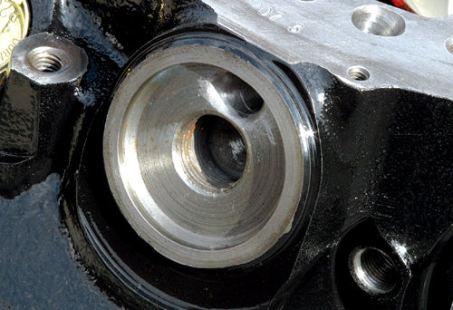
One issue facing some Cleveland blocks is oil galley indexing at main bearing saddles. If your block isn’t indexed at the bearing oil slots, chamfer the block oil passages to allow for larger volume.

From a practical standpoint, there’s really nothing wrong with the Cleveland oiling system. It makes good use of oil galleys with uniform flow to cam bearings, main and rod journals, lifters, and valvetrain. Where it falls short is in uniform distribution to these locations at high RPM.

Two lifter galleys run the length of this block without the need for a third. Both are primary oil passageways for crank, cam, and lifters with an additional galley at the back of the block for additional flow.
MCE Engines carry oil system blueprinting into galleys and passages by radiusing all passages and transitions to eliminate fluid turbulence and foaming.

Use a Melling or Ford Racing high-volume oil pump and never install it without first inspecting and blueprinting. The Cleveland’s oil pump is different with its screw-in oil pick-up, another example of cost control within this engine family.
The problem with this approach is oil starvation to main and rod bearing journals at high RPM. Main and rod bearings share oil with the lifter galleys. Traditionally, mains and rods always had an exclusive oil galley. Starvation really isn’t a fair way to put it, however, because high-performance street Clevelands have adequate oil supply to all critical points throughout the engine proving Ford engineers did their job well. However, when you spin a Cleveland to high RPM (above 6,000), oil starvation exists at main and rod journals mostly.
When Ford developed the 427 FE side-oiler, it conceived the perfect lubrication system for a high-performance V-8 with the pressure relief valve installed in the block instead of the pump, which kept pressure and volume high throughout the system. This, of course, made manufacturing quite expensive and impractical for mass production. The 351C oiling system is typical of most mass-produced V-8s of the era with the pressure relief valve in the pump where oil is control- leaked back to the pan before ever reaching moving parts.
This problem is corrected when you limit oil flow to cam bearings and lifters and divert more of it to main and rod journals where it is needed most. While you’re at it, you need to increase volume and pressure to some degree with a high-volume oil pump and some adjustment to the pressure relief valve as necessary.
Pump Blueprinting
Marvin McAfee of MCE Engines in Los Angeles has been described by Jim Smart of Mustang Monthly Magazine as something of a West Coast Smokey Yunick because he looks at engines in ways most of us never have. McAfee’s approach to engine building is methodical with extreme attention to detail. Without exception is his approach to the oil pump, which McAfee stresses must never be installed right out of the box.
“Blueprinting” is not simply engine tuning;. real blueprinting takes a closer look at things engine builders don’t always examine. Most owners install oil pumps right out of the box assuming all bases have been covered. However, oil pumps are not foolproof. They may come out of the box with all kinds of flaws and machining errors. And unless you inspect them and measure critical clearances, you’re rolling the dice on more than just an oil pump.

All pump rotor clearances must be checked. Rotor endplay should be .001 to .004 inch. Radial clearance should be .006 to .013 inch. Shaft to housing bore clearance should be .0015 to .0029 inch. If clearances are not with Ford specifications, reject the pump.

Clean up the oil pressure relief valve bore with a ball hone, then, check for freedom of valve movement. Spring pressure should be 23.6 to 24.6 pounds at 1.37 inches. If you desire more pressure, add shims one at a time.

Never use a stock oil pump shaft. Instead, order an ARP shaft (PN 154-7905) to ensure durability. The ARP shaft is made of premium aerospace grade steel and is heat-treated to 200,000 psi. If you shear an ARP shaft, you’ve got bigger problems than just the shaft.
You don’t have to take your blueprinting as far as MCE Engines does; however, there are three items you definitely need to check: G-rotor endplay, radial clearances for a full 360 degrees, and pressure relief valve function/spring pressure. If the pressure relief valve piston binds in any way, you need to chase the bore with a small ball hone until the piston glides smoothly with lubrication. If radial clearances are tight, have a machine shop examine and bore as necessary or return the pump. Rotor end clearances must fall somewhere between the minimum and maximum allowable measurements. If there’s too much clearance, you can have the housing milled to size or return the pump and hope for a better core.
Oil Control There are several approaches engine builders use with Cleveland oiling systems. Two are basically the same modification with slight variations in how they are performed. Another involves external plumbing, which routes oil from the front of the block to the back to improve bottom-end oiling, which isn’t all that effective. Yet another approach involves lifter bore sleeves that restrict oil flow to the cam and top end, which is effective and easy to perform.
When the Cleveland was introduced and used in NASCAR competition, an internally plumbed oiling system was used to feed journals number 2, 3, and 4 through drilled passages in the lifter galleys. But this is an unnecessary modification for a street or weekend racing engine. And if you’re running hydraulic lifters, you don’t want to take too much oil away from the lifter galleys.
The Cleveland oil system’s main shortcoming is too much oil to the cam bearings and lifters and not enough to the main and rod journals. So you conduct modifications that get more oil to the mains and a more conservative amount to cam journals.
The easiest oil system modification is restrictor plugs between main and cam bearing journals, which limit oil flow to cam bearings and lifters while holding more oil below for main and rod journals. Of course this isn’t as simple as screwing restrictor plugs in a block and moving on. You’ve got to know exactly what you’re doing or face the consequences of oil starvation where you need it most.
Tim Meyer of TMeyer, Inc., employs one oil restrictor plug, which gets more oil at the mains and rods and less at the cam and lifters. Though he uses a very common approach to Cleveland oil control, some cam manufacturers discourage this practice due to concern about oil starvation at the cam, lifters, and valvetrain with hydraulic lifters. It has worked successfully for Meyer and without oil starvation.
In your Cleveland engine building plan, always use a high-volume oil pump and perform a detailed blueprinting before installation. Check rotor-side clearances and the pressure relief valve for proper operation. If you want more pressure, add shims to increase pressure. However, be very careful about this because you don’t want too much pressure. You want a maximum of 10 psi per 1,000 rpm.
Written by George Reid and posted with permission of CarTech Books
LEARN MORE ABOUT THIS BOOK
If you liked this article, you will LOVE the full book!
Get your copy here.