
In almost all cases, mufflers are required in order to meet sound-level laws, especially for any street-driven vehicle. In addition, catalytic converters are required for vehicles that were originally so equipped. Here, I discuss the role that mufflers and converters play, and offer tips on enhancing both components from a performance perspective. I discuss various muffler styles, as well as catalytic converters that are available specifically designed for high-performance applications.
THIS TECH TIP IS FROM THE FULL BOOK: PERFORMANCE EXHAUST SYSTEMS
For a comprehensive guide on this entire subject you can visit this link: LEARN MORE ABOUT THIS BOOK HERE
SHARE THIS ARTICLE: Please feel free to share this article on Facebook, in forums, or with any clubs you participate in. You can copy and paste this link to share: https://www.cartechbooks.com/blogs/techtips/exhaust-systems-mufflers-and-catalytic-converter-guide
Mufflers
The muffler affects more than the engine’s sound level. As with the manufacture of tubular exhaust headers, materials include mild steel, low-grade alloy, and higher-grade 300- or 400-series stainless steel. If made of steel, muffler bodies and necks are typically galvanized or aluminum-coated. The low-grade stainless steel used by many OEMs certainly lasts longer than mild steel, but nonetheless rusts over time (and more quickly than the vehicle owner expects). If you want a replacement performance muffler to last and keep its looks, choose a manufacturer who uses 304-, 321-, or 409-grade high-density stainless steel.
Where show appearance is desired, stainless steel mufflers and tips are avail-able fully polished.

This cutaway view of Flowmaster’s 40 Series muffler shows the Delta Flow two-chamber design. The exhaust flow exits at the end near the lower portion of this photo. This design is said to minimize vehicle cabin noise while emitting a noticeable exhaust note. (Photo Courtesy Flowmaster)

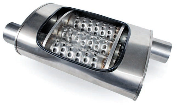
This Pro Series muffler from Flow-master provides a laminar flow and a deep exhaust tone. The flow pattern, aided by the perforations in the inner surface, allows gas flow in somewhat parallel layers that slide over one another. This design is akin to a straight-through glasspack, but with additional flow management. (Photo Courtesy Flowmaster)

Muffler designs vary widely. Shown here is a cutaway view of a Corsa RSC muffler that features a series of reversion cavities to manage sound while providing minimum backpressure. The exhaust flows through a straight tube while exhaust noise pulses enter a series of acoustic tuning chambers. (Photo Courtesy Corsa Performance)
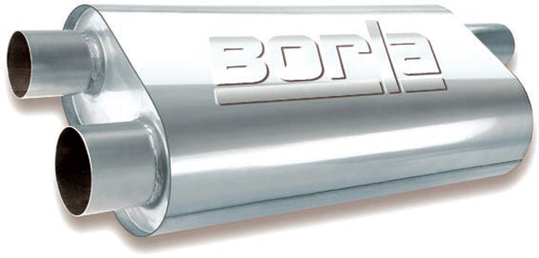
Variations of muffler connection designs accommodate single inlet and outlet styles for a single pipe on a single-pipe system or one on each pipe in a dual system. This is an example of a single muffler designed for a dual system that runs through a single muffler (Photo Courtesy Borla Performance Industries)
This muffler has a reverse-flow design where the exhaust enters through one tube, runs through a center tube in the opposite direction, and finally exits through a third tube in the opposing direction. In combination with the bleed-through perforations, specific backpressure and sound tuning is accomplished.

Variations of muffler connection designs accommodate single inlet and outlet styles for a single pipe on a single-pipe system or one on each pipe in a dual system. This is an example of a single muffler designed for a dual system that runs through a single muffler (Photo Courtesy Borla Performance Industries)

Offset inlet/outlet mufflers are often needed to provide a better fit, due to pipe locations and available undercar space. (Photo Courtesy Borla Performance Industries)

If you decide to use oval exhaust pipe, mufflers are available with oval inlets and outlets, so no round-to-oval modifications are necessary. Oval exhaust pipe is a popular choice where ground clearance is an issue. (Photo Courtesy Borla Performance Industries)

This pipe to the muffler has a short “branch” pipe that helps to reduce exhaust drone. This is yet another way that muffler manufacturers can alter the audible frequencies created by the exhaust path.

In situations where the pipe entry to the muffler differs in plane from the outlet pipes, offset inlet/outlet muffler designs solve clearance and fitment issues.

Here, a chambered exhaust pipe serves as both the pipe and muffler. An internal flow tube has perforations, or louvers, into which the sound waves enter. The sound waves then hit the crimps, or dents, placed strategically along the outer shell, effectively tuning the exhaust note. The size of the perforations/louvers and the location of the outer tube crimps affect the sound. Spacing and size of the perforations vary depending on the manufacturer’s design, often “tuned” for specific vehicle/engine applications.

Once the inner flow tube is placed inside the outer pipe, the outer pipe is crimped to lock the flow tube in place and to establish the exhaust sound. No packing sound-absorption matting is used in a chambered exhaust pipe.

Glasspacks are straight-through mufflers that have an internal perforated tube with sound-absorbing packing material sandwiched between the inner and outer tubes. Glasspacks are available in a variety of lengths. Even extremely short glasspacks, such as this one, are available for applications where the sound level needs to be reduced a bit while providing the desired tone. (Photo Courtesy Cherry Bomb)

This is an example of a race-application chambered muffler. The compact design and free-flow capability of this Extreme model accommodates an application where space is at a premium. (Photo Courtesy Cherry Bomb)

This illustration shows the flow pattern of an Extreme muffler. Red indicates exhaust gas flow and blue indicates tonal, or noise, reduction. (Photo Courtesy Cherry Bomb)

This Corsa muffler for a 2012 Mustang V-6 bolts on and features OEM bends and welded-on hanger pegs that slip into the OEM rubber hanger locations. (Photo Courtesy Corsa Performance)

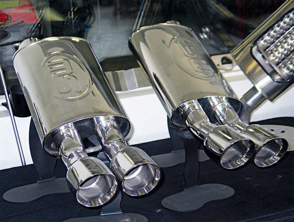
Instead of having to add chrome or polished exhaust tips, some systems are available with polished stainless tips already installed. This is an example of a muffler setup for the ZR1 Corvette. (Photo Courtesy Corsa Performance)

This illustration of the Corsa RSC muffler provides a clear understanding of its noise-canceling design. As exhaust noise enters the main tube, the sound waves bleed off into the low-frequency channels, resulting in a reflected out-of-phase pulse that diminishes noise while allowing a non-restricted flow of exhaust pressure. (Photo Courtesy Corsa Performance)
The primary goal of any muffler is to reduce the noise level (dBA) to a tolerable range to suit both passengers and anyone outside the vehicle. Noise levels are legislated by government and are also mandated by many racetracks in order to appease those who live within earshot of those tracks.
To achieve this noise reduction, muffler styles can feature chambers, baffles, perforated internal tubes, and/or a sound-deadening material.
Muffler Types
Three basic types, or styles, of mufflers are commonly available. These are chambered, turbo, and straight-through.
Chambered mufflers feature a series of internal chambers and/or baffles. As the exhaust pulse enters the muffler, the sound waves bounce and reflect through and off these walls or cavities, causing the sound waves to bounce against each other. These sound waves cancel each other out, which reduces noise. Each muffler manufacturer follows its own design in achieving this. Essentially, chambered mufflers use sound-canceling technology to reduce noise while producing a desired sound level and exhaust note tone, with varying designs that appeal to stock replacement or high-performance sound attributes.
Chambered mufflers feature internal chambers, or rooms, where the exhaust flow is diverted. Muffler manufacturers use various designs, but the goal is the same: to manage sound and pressure by means of the flow path, tuning the muffler design with both sound and backpressure performance in mind. Performance muffler manufacturers go to great lengths to create innovative chambering designs. As far as sound is concerned, it can vary from extremely quiet street versions to extremely loud race versions.
Chambered exhaust pipe serves as both piping and muffler in one unit. A chambered muffler has the appearance of an exhaust pipe with a series of crimps, or dents, along the body. Inside the outer tube is a core tube that has perforations or louvers, often called a flow tube. As the exhaust flows through the pipe, sound waves enter the perforations or louvers, causing them to hit the crimps in the outer tube. This creates turbulence in the sound waves that “tune” the exhaust sound. Chambered pipes don’t include any sound-absorbing packing material, and are usually nice and loud with a raspy sound. These are straight-through pipes; they tune the sound by altering the sound waves.
The turbo-style muffler commonly features perforated internal tubes that snake the exhaust flow through the muffler in an S pattern, providing added tube length inside the muffler. An inlet tube directs the exhaust into an open chamber that then diverts the flow 180 degrees through a second tube, where the exhaust flow is again diverted another 180 degrees through a third tube, with the flow finally exiting the muffler.
Turbo mufflers have nothing at all in common with a spinning turbine. The term is simply used as a marketing catch phrase. A turbo-style muffler commonly has an S-bend flow path inside the muffler housing. The flow enters, runs through a certain distance in a straight path, then turns 180 degrees, runs straight, then makes a final 180-degree turn. Along the way, perforations may be present along with sound-deadening packing. Typically, a turbo-style muffler offers increased sound reduction and is typically a quieter muffler as com-pared to other styles.
Straight-through muffler styles offer a direct path for the exhaust from entry to exit, with no diversions or wave-reflective walls. An internal perforated pipe is wrapped in a sound-deadening material for noise absorption. This design offers less restriction and is more compact (typically bullet shaped or round canister shaped), making a straight-through muffler easier to locate in terms of available space.
Straight-through mufflers feature exactly what the term implies: an uninterrupted flow from entry to exit, with no chambers or baffle walls in the way. This style has a perforated inner tube with a sound-deadening material, typically fiberglass, packed between the perforated tube and main housing. Sound waves enter the perforated tube and are absorbed, to a degree, by the packing. Straight-through mufflers are often referred to generically as glasspacks.
Muffler Assembly
Muffler shell profiles are typically either round or oval. Round shells are usually made with a round tube as the main body, or by forming a flat sheet into a round profile with inlet and outlet necks welded in place. Some straight-through glasspacks are formed from a tube with the inlet and outlet necks reduced to the appropriate diameter through hydroforming. This is done in a two-piece die. The tube is placed into the die, the die halves are mated together, and water is injected at extremely high pressure, forcing the tube to conform to the shape of the die.
When muffler shells, either round or oval, are formed, the manufacturer begins with flat stock metal that is rolled to shape. The seam is then TIG welded, either by hand or by robotic welding.

Hydroforming allows a muffler body to be made without multiple sections, such as main canister and tips. This glasspack muffler body was formed at the Corsa factory starting with a piece of straight tubing, using high water pressure with the straight pipe captured inside a die.

Hydroforming uses extremely high water pressure to expand and form a piece of pipe into a specific shape. A two-piece die is positioned in the machine. With the precision-machined dies mated together, water pressure is injected into the pipe, forcing the pipe to conform to the die. Due to the expense of making the dies, hydroforming is only used in rare applications where welded seams are not desired.

Muffler body shells are initially formed on a roller. This allows the maker to form either a round or oval body shell. Here a sheet of stainless steel is rolled through the forming machine to create a round shell.

Here a group of round forms are ready to proceed to seam welding at Corsa’s factory.

These stainless steel oval shells are ready for seam welding at Stainless Works.

Muffler shell seams are TIG welded before assembly. Depending on production schedules or shell design, seam welding can be done by skilled welders or with the use of robotic welders. Here a craftsman at Stainless Works seam welds a muffler shell.

For certain applications, perhaps high-production runs, robotic welders are employed for muffler-shell welds.

Once fully assembled, the muffler end caps are TIG welded. (Photo Courtesy Corsa Performance)

Muffler assembly takes place before end-cap installation. Here perforated internal pipes are wrapped in a steel wool sound-absorption matting and inserted into the shell.

This muffler design features a staggered internal-perforated pipe wrapped in sound-absorption matting with the remaining cavity also stuffed with matting. This is essentially a straight-through muffler with plenty of sound-absorbing capacity. Decibel levels are determined by the design of the application. There is no standard in terms of decibel levels; it varies by manufacturer, diameter, and length of the muffler.

A collector muffler is ideal for applications in which no additional exhaust pipe is used and therefore a sound-absorbing collector muffler serves to aid in scavenging and provide minimal tone management. (Photo Courtesy Borla Performance Industries)
Sound-Absorption Packing
Sound-absorption materials are commonly referred to as packing. They are used in a variety of muffler designs and can vary depending on the manufacturer and the muffler model. Materials include fiberglass matting, steel wool, stainless steel mesh, and other proprietary high-temperature acoustical-suppression materials.
Mufflers that use a packing sound-absorption material feature one or more perforated tubes inside the main housing. Exhaust enters the perforated tube and bleeds out through the perforations into the packing material, which serves to absorb sound. The theory is akin to early-generation silencers used on some firearms. The exhaust pressure is able to travel through the internal pipe, with sound pulses dampened or filtered by the packing material.
Some muffler designs feature a single layer of sound-absorbing material (fiberglass or other material). Other designs use two layers: a steel wool or stainless steel mesh as the first layer wrapped around the perforated tube and a second outer layer of fiberglass or other material. The reason for using steel wool or stain-less steel mesh is to both affect the exhaust sound and to provide a protective boundary layer that prevents the more-fragile outer layer of material from “blowout.” This dual-layer approach provides increased durability to the assembly.
Matting Replacement

Here’s a perforated inner tube (left) next to the main muffler body (right). (Photo Courtesy Burns Stainless)

Here’s an example of a do-it-yourself service-able straight-through glasspack muffler, primarily intended for racing use. The inlet head and perforated inner tube is a separate piece, secured to the main housing with setscrews. (Photo Courtesy Burns Stainless)
Step: 1

The head and inner tube is removed from the muffler housing by removing the setscrews. (Photo Courtesy Burns Stainless)
Step: 2

After removing the worn-out matting, new sound-absorbing matting is wrapped around the perforated tube. Rather than using sound-deadening materials available from local hardware stores, it’s best to purchase the material directly from the muffler manufacturer. Choosing incorrect material can lead to muffler obstruction or objectionable exhaust sound. (Photo Courtesy Burns Stainless)
Step: 3

The matting is secured to the perforated tube with tape. The tape is somewhat sacrificial, only used to hold the matting in place during installation. Although masking tape is adequate, heat-resistant foil tape similar to that used for furnace ducting is better. (Photo Courtesy Burns Stainless)
Step: 4

The wrapped tube is inserted into the muffler housing. (Photo Courtesy Burns Stainless)
Spiral Inserts
An alternative to using a conventionally installed muffler is the spiral insert. This is a straight section of small-diameter pipe upon which a series of spiral blades are welded, making the unit look like an auger. The spiral unit is installed as an insert into a straight section of the existing exhaust pipe.
You can refer to this type of product as a baffle insert, which is installed much like a baffle tube on a motorcycle engine’s exhaust. The baffle slips into a straight section of exhaust pipe and is anchored in place with two small setscrews. Spiral inserts are available in a wide variety of diameters, lengths, and number of spiral blades.
Selecting the diameter of a spiral muffler is easy. Simply choose a diameter that fits inside your existing exhaust pipe. For example, if you’re running 3-inch pipe, you need an insert designed to fit a 3-inch pipe ID. As far as length and number of spiral blades is concerned, the experts at Spiral Turbo Specialties and others can offer their recommendations, based on the type of sound that you desire, engine displacement, engine horse-power, heads, and cam.
Spiral Turbo Specialties makes three basic types: the 3-flight that is 8 inches long and features three spiral blades, the 4-flight that is 12 inches long with four spiral blades, and the 9-flight that is 30 inches long and has nine spiral blades. The 30-inch version is commonly used for side-pipe applications, such as those found on Corvettes and Cobras.
Their recommendation for location of the baffles is to place them as far back as possible, as close to the tips as possible, in order to produce the best sound and to eliminate any potential droning issues. In general, the greater number of spiral blades, the quieter the system. As the number of blades decreases, sound increases. Another sound-tuning aid is found in the baffles’ center tube, which is capped. Once installed, if you desire a louder sound, simply remove the baffle and drill out the cap with a 7/8- or 1-inch hole.
One of the extremely beneficial features of a spiral insert involves installation space. Because the insert is installed inside a section of straight pipe, it’s invisible from the outside.
With no increased dimensions relative to the pipe, this style saves room, with no need to locate the muffler according to the frame, crossmembers, etc. It’s a real space-saver. An added benefit is in appearance. With the baffle hidden inside the pipe, the exhaust system looks like an open sans-muffler setup.

A spiral insert consists of a steel tube with a series of spiral blades that serve as exhaust diverters.
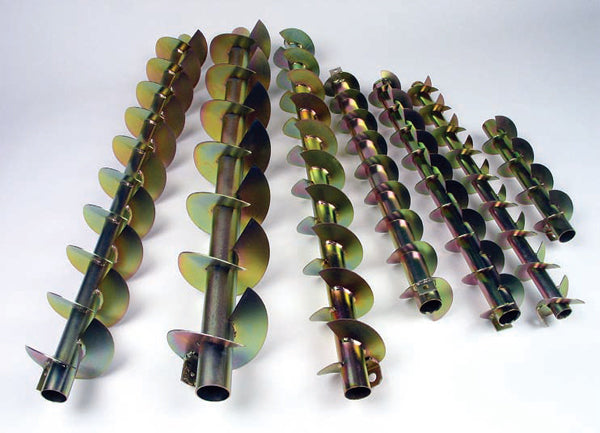
Spiral inserts are offered in a variety of lengths, diameters, blade counts, and blade pitches to accommodate different sound and performance levels.

Once you’ve drilled the two holes in the pipe to align with the holes in the baffle’s mounting tabs, slide the insert into the straight pipe.

Align the holes and secure the baffle with stainless steel button-head screws. This makes future removal easy if you want to switch from baffled to open.

Spiral exhaust baffles can be installed in any section of straight pipe, including exhaust tips.

This clone of a 1964 Comet AFX features a very simple exhaust setup, with straight pipes running from the header collectors mated to 45-degree pipes that exit in front of the rear tires. While the car looks like an old-school drag car, the owner intends to drive it on the street only. To provide a straight-through exhaust appearance while managing the noise level, the 45-degree tips feature hidden spiral baffle inserts. This was a clean way to provide a race appearance while avoiding a ticket for loud exhaust.
Selecting length and number of blades for any given pipe diameter allows you to tune for sound and performance. The owner and designer of Spiral Turbo Specialties, Jim Laughlin, has invested in countless hours of chassis dyno and road testing and development to create these baffle inserts for a wide variety of both street and track fitments, including gas and diesel applications. Jim offers baffle diameters in 11 sizes ranging from 2.25 inches all the way to a whopping 10-inch diameter for commercial Diesel semi-tractors. A recent addition to the line is the tapered baffle for installation to lake-pipe headers or cone-shaped exhaust pipe on street rods.
As an example, my shop recently built a 1964 Comet AFX clone for a customer who wanted side-exit exhaust pipes, located immediately ahead of the rear wheels. We simply ran 2.5-inch pipe from the header collectors, straight back toward the rear and added 45-degree bends, with a slash cut at the tips (so that the tip ends were cut parallel to the body). Instead of adding in-line mufflers, we installed spiral baffles, one in each tip’s straight section.
The 45-degree bends with the straight exits were made of stainless steel and polished. The baffles feature two mounting tabs with threaded holes. The exit pipe was drilled to provide holes that aligned with these mounting tabs. The inserts were then secured with stainless steel button-head screws.
The baffles we chose provided a nice raspy tone with minimal restriction that was ideal for the street. Whenever the owner wishes to remove the baffles, all that’s required is to remove the two setscrews and pull the baffle out directly from the exhaust pipe tip, with no need to crawl under the car. Especially if space is an issue, this is a sound-management approach worth considering. Backpressure is minimal with the spiral inserts.
Mufflers adjust sound by any of a number of methods, including damping sound waves through sound-absorbing packing material or by allowing waves to be directed by partial walls or into chambers.
Years ago, I saw a prototype exhaust system at the research center of one of the major OEM and after-market replacement exhaust system manufacturers. It had developed a unique sound-canceling system that used amplified sound waves. The system didn’t have a muffler in the traditional sense and the exhaust passed straight through the system with no restriction.
Sound control on this prototype was a microphone that picked up the sound waves created by the engine as they passed through the pipe. The sound or frequency waves that were monitored were then fed through a processor that created a mirror image of the waves, instantly creating the same wave, which was transmitted back to the exhaust via an amplifier and speaker. The result was a cancellation of the exhaust sound.
This noise cancellation process proved to be too expensive and required too much space under the vehicle to be practical, but the theory was solid. Many of today’s muffler manufacturers utilize a form of noise cancellation in their designs with the use of diversion walls and resonance chambers, tuning the design to cancel specific frequencies.
Resonators
Some OEM vehicles have a resonator. It is essentially a sound-tuning device that’s added to the system, either before or after the muffler, to adjust the sound frequency. A resonator is a straight-through canister that may or may not have internal sound absorption. If an OEM vehicle was equipped with a resonator, removing the resonator doesn’t affect power, but it alters the exhaust note (perhaps louder or with a different frequency). Resonators are all about sound quality; the carmaker adds them when they feel the need to “tune” the sound. From a performance standpoint, either for the street or track, the addition of a resonator is not common.
Another method that many OEMs (and some aftermarket exhaust makers) use to reduce or eliminate bothersome exhaust drone is to use “branches” along the exhaust system. This involves installing a short pipe 90 degrees to the exhaust pipe, just ahead of the muffler, that is capped off or that enters into a separate chamber of the muffler. This provides a small side pocket of volume; it is similar to a river that has a small branch-off stream. The exhaust noise enters this short branch and is captured within the capped-off branch, altering the frequency of the exhaust note. Of course, development testing is involved in terms of the branch diameter and length.

Tapered lake-pipe headers can also accommodate this type of insert baffle.

This chart shows the chassis dyno results for a stock 2008 Pontiac G8 GT with stock exhaust system. Horsepower at the drive wheels was recorded at 285.37 hp with torque at 308.11 ft-lbs. (Graph Courtesy Spiral Turbo)

The same car on the same chassis dyno, with the stock mufflers removed and 3-inch spiral baffles installed produced 302.92 hp and 318.88 ft-lbs of torque. (Graph Courtesy Spiral Turbo)

As an experiment, the same Pontiac, still equipped with the 3-inch baffles, was then switched from 87-octane fuel to 91-octane fuel. This increased horse-power to 311.70 and torque at 333.48 ft-lbs. (Graph Courtesy Spiral Turbo)
For instance, if the exhaust note that matches the frequency of the tires as they roll down the highway hits a certain sound frequency, an objectionable hum or drone may result. A resonator might then be added to alter the frequency of the exhaust note to avoid this noise. OEMs use specialized frequency-monitoring data-collector equipment to develop a resonator for a specific application, which is out of reach for hobbyists. Several performance aftermarket exhaust system manufacturers have already developed exhaust system packages for specific vehicles to address this issue of annoying frequencies, by virtue of muffler design or by adding a resonator.
Catalytic Converters
Internal combustion engines essentially operate as air pumps. In over-simplified theoretical terms, the more air that can be introduced into the combustion chamber (along with the proper ratio of air and fuel), the more horsepower that can be produced. OEM and performance aftermarket engineers continually strive to increase the efficiency of cylinder head intake runners and combustion chambers, piston domes, camshafts, valves, intake manifolds, carburetors, and throttle bodies, etc. Along with increasing intake air, the exhaust system must be designed equally as efficient in order to complement the engine as a total system.
Components that control or have an effect on the exhaust flow of the engine are:
- Camshaft profile
- Exhaust valve
- Cylinder head design
- Exhaust manifolds/tubular headers
- Turbocharger or supercharger
- Exhaust tubing diameter and length
- Catalytic converter
- Muffler
An exhaust system that reduces the amount of work required for the engine to push the exhaust gas translates into reduced energy loss and that (theoretically) translates into power output. Remember: Horse-power isn’t free; as you increase air intake, you also need to increase fuel. The exhaust system must not only decrease flow restrictions and increase airflow, but also allow the engine’s fuel system to manage the correct air/fuel ratio (not too lean and not too rich).

The original mufflers were removed and a spiral baffle was installed.

Straight tip sections equipped with spiral baffles simply clamp onto the existing pipes.

There’s no reason that a catalytic converter needs to look boring. Performance aftermarket converters are available with polished stainless steel housings to better coordinate with a performance exhaust system. (Photo Courtesy Eastern Catalytic)

Catalytic converter assemblies are available for direct replacement fit on production vehicles that better suit street-performance requirements. This example features a built-in H-pipe crossover immediately after the header collectors. Performance aftermarket assemblies come in stainless steel as well as ceramic-coated versions for increased durability. (Photo Courtesy Eastern Catalytic)
THIS TECH TIP IS FROM THE FULL BOOK: PERFORMANCE EXHAUST SYSTEMS
For a comprehensive guide on this entire subject you can visit this link: LEARN MORE ABOUT THIS BOOK HERE
SHARE THIS ARTICLE: Please feel free to share this article on Facebook, in forums, or with any clubs you participate in. You can copy and paste this link to share: https://www.cartechbooks.com/blogs/techtips/exhaust-systems-mufflers-and-catalytic-converter-guide
Airflow is influenced by the diameter of the exhaust system as well as the speed in which the exhaust gas is moving.
Exhaust Flow = flow velocity x area
Where:
Flow Velocity = mass ÷ speed Area = mass2
As you increase airflow only by increasing exhaust tube diameter, you likely decrease air velocity. A performance exhaust system needs to be designed to produce as little back-pressure as possible while maintaining the high-flow velocity required for cylinder scavenging. A catalytic converter’s purpose is to reduce engine emissions, specifically carbon monoxide, hydrocarbons, and oxides of nitrogen. The converter attempts to burn off carbon monoxide and unburned hydrocarbons, while converting oxides of nitrogen back into harmless nitrogen.
A washcoat applied to a ceramic honeycomb core is used to chemically treat contaminants. These washcoats can include material such as aluminum oxide, titanium oxide, and silicon dioxide. These react with the exhaust content to wash emission particles. The catalyst is usually made of a precious metal such as platinum, palladium, or rhodium.
As far as a catalytic converter’s role in exhaust system backpressure is concerned, researchers have found that performance does not increase with the increase of back pressure. Even pressure levels of 2 to 5 psi in the exhaust system can adversely affect engine performance. This positive backpressure slows the exhaust velocity, causing uneven scavenging of the combustion chamber and making the piston fight harder on the combustion stroke, as well as reducing or diluting the oxygen content coming into the cylinder through the intake plenum. Further complicating the situation, during overlap of the intake and exhaust valve timing, the positive pressure from a poorly designed exhaust system can actually dilute adjacent cylinders, pushing exhaust gas into the intake plenum and throttle bodies.
In recent years, even OEMs have recognized the need for catalytic converters that address the needs of the performance enthusiast. This has resulted in high-flow converters being introduced on some new vehicles while maintaining required emissions levels.
The catalytic converter is simply part of the exhaust system, with the specific responsibility of reducing emissions. When creating a performance exhaust system, the common trend involves using larger-diameter exhaust tubing and high-flow mufflers in an effort to reduce back-pressure and to promote exhaust scavenging.
However, as far as catalytic converters are concerned, you actually want the exhaust gas to go through the converter substrate at as slow a rate as possible to allow time for the chemical reactions to take place. While these reactions take place in microseconds, a catalytic converter requires the exhaust gas to remain in the converter for a period of time that is determined by the length of the converter’s substrate and the exhaust flow velocity. Converter bodies typically feature a larger diameter than the inlet pipe, which slows the exhaust flow velocity, which in turn provides additional time for the catalyst reaction to take place.
Additionally, the larger volume inside the converter permits the use of a larger substrate to promote exhaust gas emissions reduction. As the exhaust flow leaves the converter, the converter necks-down in diameter to increase the exhaust velocity once again. Manufacturers of high-quality catalytic converters are ever mindful of sizing the converters to match the engine manufacturer’s requirements for airflow and backpressure.
Volumetric efficiency and maximum engine RPM can play an important role in the selection of a correctly sized catalytic converter. Going to a larger converter doesn’t gain anything.
Cat-Back Systems
A cat-back system refers to after-market exhaust system piping and mufflers that can be installed after the catalytic converters. It is used by owners who wish to enhance exhaust flow and sound on a converter-equipped street vehicle, without disturbing the converter’s emissions handling. Those who prefer not to upgrade to tubular headers use it. Rather than starting from scratch by replacing the entire exhaust system, a cat-back setup allows a mild upgrade for the least amount of money and labor time.
Cat-back systems enhance the exhaust system by replacing the pipes and muffler(s) without removing or replacing the converters. They are readily available for a wide range of production vehicles as a direct bolt on from the converters to the end of the tailpipes. A cat-back system allows an easy upgrade in terms of added performance and altered sound.

A catalytic converter’s job is to scrub harmful emissions, including carbon monoxide, hydrocarbons, and oxides of nitrogen. A well-designed performance converter avoids an increase in backpressure while also capturing the flow long enough for the chemical and thermal reactions take place. (Photo Courtesy Eastern Catalytic)
Some systems are quiet, with minor performance and sound change, while others provide notable changes. The results largely depend on the specific engine and the design of the replacement mufflers. Selecting a cat-back system is simple. Choose a reputable brand that features the muffler style you prefer.
Cat-back systems are premade to fit popular production vehicles, so you don’t need to worry about modifications in order to accommodate the installation. They are easy to install and typically mount in the stock pipe and muffler locations, using the existing OEM hanger locations. A cat-back system that’s made of stainless steel is preferable in terms of longevity. Cat-back systems also commonly feature crossover pipes.
Diagnosing Catalytic Converters
When a converter fails by plugging up, or experiencing reduced conversion efficiency that results in not being able to pass an emissions test, the root cause of the failure usually lies elsewhere. In other words, something upstream from the converter probably caused the converter to fail. Possible culprits can include an overheated engine, chemical contamination, vacuum leaks, the EGR system, fuel injectors, spark plugs, oxygen sensors, improper engine assembly techniques, etc.
Some converter failures should make you look elsewhere in the engine for the real cause of the problem. Unfortunately, some failures caused by these problems are not covered by the manufacturer’s warranty.
Overheating
Catalytic converters are designed to tolerate substantially high temperatures, often up to 2,000 degrees F. Severe overheating can destroy converter matting and even melt substrate coatings, and can even lead to clogging of the converter. For example, if the engine has experienced leaks in the exhaust system, upstream of the converter, it can result in elevated converter temperature. Typically, a converter temperature needs to be brought to about 350 to 500 degrees F to “light off” (for the substrate to do its job). This range varies depending on the application and the location of the converter relative to the cylinder head(s).

The melted ceramic brickin this damaged converter indicates that the engine was runningtoo hot. An excessively lean air/fuel mixture may have caused this. Replacing the brick is not an option;the converter must be replaced. (Photo Courtesy Eastern Catalytic)

This oil-fouled ceramic brick is a tell-tale sign that engine oil had entered the exhaust system. This could be due to worn piston rings, worn valve seals, excessive crankcase pressure, etc. An oil-fouled converter must be replaced. (Photo Courtesy Eastern Catalytic)

Evidence of RTV on this exhaust manifold flange is an indication of oxygen-sensor contamination. (Photo Courtesy Eastern Catalytic)

This oxygen sensor has been contaminated by an attempt to use Teflon tape to seal the sensor threads. (Photo Courtesy Eastern Catalytic)
Converter Contamination
Several things can easily contaminate the substrates used in converters. For example, if anti-freeze enters the exhaust stream as the result of a cracked cylinder head, cracked block, warped cylinder head, and/or failed head gasket, the substrate can be contaminated easily, rendering the converter ineffective. The converter can also foul if engine oil enters the exhaust system as a result of worn piston rings, valveguides, or seals.
If incorrect sealants are used during assembly of intake manifolds, exhaust manifolds, etc. that contain high levels of silicone or Teflon, the system can outgas when exposed to high heat. This outgassing can then leave a residue on the oxygen sensors and in the converter.
Whenever you’re using a sealing compound on an engine that features a catalytic converter and/or oxygen sensors, make sure that the sealant is “sensor safe.” Using the wrong sealant can ruin a converter by reducing its efficiency.
Testing the Converter
If you suspect a blocked/plugged catalytic converter, you can perform a vacuum test. First, connect a vacuum gauge to a vacuum port on the intake manifold, carburetor, or throttle body. Read and record the vacuum at engine idle. Next, run the engine to 3,000 rpm and hold it at that speed. The vacuum should drop when you first open the throttle, but should then rise and level off. If the vacuum reading starts to drop, this can indicate that pressure is building in the exhaust system, which points to a restriction in the exhaust system. The converter, the muffler, or a foreign object stuck inside the piping can cause the restriction.
If you suspect a non-working converter, a common test used to be to check the temperature before and after the converter because it was accepted practice to expect about a 100-degree F difference in temperature from the inlet of the converter to the outlet. However, today’s late-model fuel injected engines have become so efficient that this test may not provide an accurate means of determining converter function.

The discoloration on this converter body indicates excessively high exhaust temperatures. (Photo Courtesy Eastern Catalytic)

The plugged ceramic brick in this converter indicates incomplete combustion by-products, likely resulting from a too-rich engine condition. Catalytic converters are not repairable; any converter that has been damaged or fouled must be replaced. (Photo Courtesy Eastern Catalytic)
In late-model systems, the converter may cool down so rapidly that you are not be able to read much of a temperature difference at idle, and you might only see a difference of 50 degrees or less with the engine revved to 2,500 rpm. With this in mind, a temperature check is still worthwhile to determine if the converter is performing properly.
Using an infrared pyrometer (a point-and-shoot non-touch thermometer), check the inlet temperature (at the front weld ring of the converter). The temperature should be 350 degrees F or higher. Then check the temperature at the outlet, at the rear weld ring. The temperature should be about 100 degrees higher. If the temperature is more than 500 degrees F, it may indicate overheating caused by a number of issues upstream.
Before you blame the converter, check for vacuum leaks, improper fuel mixture, and exhaust leaks at the manifold, header flange, cylinder head, etc.
Break In
Breaking in a converter may sound odd, but it’s important for avoiding long-term problems. Just as new piston rings need to be broken in and seated to the cylinder walls and flat-tappet camshafts need to be broken in with their lifters, a new catalytic converter also requires a break-in period to provide the expected service life and efficiency. The issue deals with the required expansion of the converter matting that holds the substrate in place.

This fuel trim data indicates that a rich condition commands the on-board engine management computer to lean the fuel mixture. A lean condition commands a richer mixture. (Chart Courtesy Eastern Catalytic)

This is a sample screen shot on a diagnostic analyzer while load testing the efficiency of a catalytic converter. The percent of efficiency that each converter manufacturer tries to achieve may differ. If the rear oxygen sensor oscillates up and down, it is indicative of an inefficient converter. A properly operating catalytic converter should be 90 percent efficient. In other words, 90 percent of the hydrocarbons and carbon monoxide that enters the converter should be scrubbed by the converter. In this example, a used converter that is determined to be only 53 percent efficient has failed and should bereplaced. (Photo Courtesy Eastern Catalytic)
Here is an example of catalytic converter efficiency during a no-load condition. (Photo Courtesy Eastern Catalytic)
A catalytic converter’s ceramic brick is wrapped with matting that insulates it and holds it together. The matting is made from the mineral vermiculite, which is secured by a fiber mat and an organic binder. As the converter heats up during its first use, the fiber mat and binder burn off and the matting actually becomes looser before it expands to fill the converter cavity to hold the ceramic brick in place. If the proper break-in warmup is not performed correctly, the ceramic brick can loosen and can rattle inside the converter housing.

This temperature expansion graph illustrates how the converter matting expands as converter temperature increases during the initial warmup cycle. Ignoring catalytic converter break-in can result in inadequate matting expansion, which may lead to brick vibration and damage. (Graph Courtesy Eastern Catalytic)

This is a cutaway view of a typical catalytic converter with matting and a ceramic block. (Photo Courtesy Eastern Catalytic)

Matting is installed in its initial unexpanded state (right) to ease installation and assembly of the converter. Once exposed to exhaust heat, the material expands (left) to fill the voids. This expansion occurs during the converter’s break-in period. (Photo Courtesy Eastern Catalytic)
Warmup Heat Cycling
For the matting to expand properly and to provide long converter life, follow these simple steps:
- Start the engine but do not rev it.
- Idle the engine and allow it to warm up slowly.
- After 5 minutes, increase the engine speed to 2,500 rpm.
- Hold at 2,500 rpm for 2 minutes.
- Allow the engine to cool down.
- Road test to confirm correct installation.
Written by Mike Mavrigian and posted with permission of CarTech Books
THIS TECH TIP IS FROM THE FULL BOOK: PERFORMANCE EXHAUST SYSTEMS
For a comprehensive guide on this entire subject you can visit this link: LEARN MORE ABOUT THIS BOOK HERE
SHARE THIS ARTICLE: Please feel free to share this article on Facebook, in forums, or with any clubs you participate in. You can copy and paste this link to share: https://www.cartechbooks.com/blogs/techtips/exhaust-systems-mufflers-and-catalytic-converter-guide