
In this chapter I cover taking the transmission apart for rebuilding and note each part. I also provide specific guidance and tips along the way to make the job easier. Transmissions have a lot of parts, and it helps to group them together during removal so it’s less confusing later on when you start cleaning and inspecting them for reassembly.
This tech tip is from the full book, GM TURBO 350 TRANSMISSIONS: HOW TO REBUILD & MODIFY.
For a comprehensive guide on this entire subject you can visit this link: LEARN MORE ABOUT THIS BOOK HERE
SHARE THIS ARTICLE: Please feel free to share this post on Facebook Groups or Forums/Blogs you read. You can use the social sharing buttons to the left, or copy and paste the website link: https://www.cartechbooks.com/blogs/techtips/gm-th350-transmission-disassembly-guide
You do not have to be as concerned with how clean the transmission is during the disassembly process as you do when putting it back together. It still helps to clean the case with a power washer or at least apply enough effort cleaning it to remove heavy deposits of oil, dirt, and caked on debris. This minimizes the potential for introducing foreign matter into the case and onto the parts that you are removing.
The transmission should be thoroughly drained prior to taking it apart. The best method to accomplish this is to put it in a holding fixture for several hours with the tail housing down and a large drain pan under it. Some fluid will still be trapped under the valve body, under the accumulators, and in the case oil passages. Be prepared and keep a large pan under the transmission the entire time.
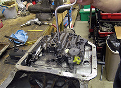
The used TH350 transmission is secured in the holding fixture and is mounted on the workbench. I have cleaned off a work area and rounded up the tools needed to take the unit apart for inspection. This particular unit was pretty clean. Some units require a good power washing to remove dirt, mud, grease, and road grime before they are taken apart.

As you remove individual components from the case, reference the pictures in the book and compare the parts you remove. As each item is lifted out, place it on a clean tray or shop towels in the same position that it was in the case. Be sure to always look on the bottom of each piece as you remove it; it’s quite common for thrust washers to stick to the component being removed and not be present on the next component in the case. Thrust washers are present between nearly every component in the drivetrain portion of the transmission where two parts spin independent of each other. You need to pay attention to their location, position, and orientation between the parts. Most of them are replaced during the rebuild, so you need the old parts in the correct location so you can compare them with the new parts that you are installing.
The TH350 underwent several changes during its production years. Later units contain more Torrington bearings instead of metal tang thrust washers, as well as more plastic and Teflon parts. Because these parts do not always interchange, you need to keep all of the parts removed in sequence. You must note their position in the transmission when they were removed, so that you can get the correct parts in the correct place and in the correct orientation later on during assembly.
Proceed with confidence. Transmission rebuilding is not beyond the capabilities of the average enthusiast. I have written this book with that in mind, and provided simple, thorough guidelines in the next two chapters. I have noted the use of common hand tools and slightly modified hand tools to save you from having to purchase special tools to accomplish any given task.
Oil Pan and Valve Body Removal
Step 1
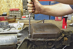
The transmission pan bolts are removed first. Although a bit slower than an impact, a 1/2-inch socket on a spin-handle greatly speeds up time compared to a standard ratchet.
Step 2
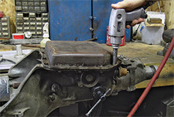
Using an air impact gun speeds up the process considerably. Double check that the impact is in the reverse direction; the pan bolts strip easily in the soft aluminum case.
Step 3
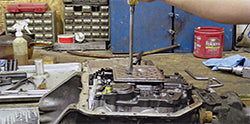
Remove the two slotted 1/4-20 screws that hold the filter to the valve body. A separate gasket for the filter is located between the parts.
Step 4
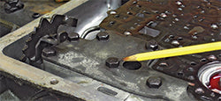
Make sure that the kick-down cable has been removed from the case. Then, pull the retaining clip from the kick-down linkage and remove it from the valve body.
Step 5
The S-link is connected to the manual valve and linkage. Once all of the valve body bolts have been removed, it slips easily out of the valve.
Step 6
Use an air impact to remove the 5/16-18 valve body bolts. Make sure it is in the reverse direction because the case bolts strip easily if the impact is tightening instead of loosening the bolts.
Step 7
A spin-handle and 1/2-inch socket is a safer and faster method to remove the valve body bolts.
Step 8
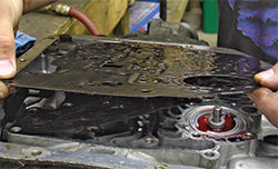
Once all of the bolts are removed, gently lift the valve body off of the case. It may stick to the gaskets and tear them during removal. Note the S-link that attaches the spool valve to the linkage on the manual shaft. The spool valve slides out of the valve body when it is removed. It is easily bent or damaged if it hits the hard concrete fl oor. Remove the spool valve and S-link from the valve body and set them aside to avoid damaging them.

Servo Assembly Removal
Step 1
Note the accumulator location in the valve body. It has a spring under it and a clip retains it.

Step 2
The servo assembly that applies the band is located under the valve body in the case. The accumulator will be removed later. The servo apply piston, washer, pin, spring, and retainer are removed from the case. Set these parts aside; they will be reused. Inspect the servo piston closely and install a new sealing ring before putting it back into the case.
Step 3
Grasp the servo assembly by the apply pin and remove it from the case. Under the servo piston is a washer, retainer, and spring—in that order. Keep these parts together for use later during assembly.
Support Plate, Separator Plate, Check Balls and Filters Removal
Step 1
A flat support plate holds the valve body separator plate and gaskets in place. It must be removed before the separator plate can be removed.
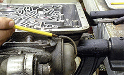
Step 2
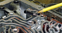
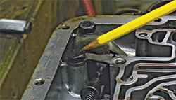
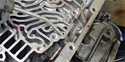
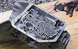
Once the support plate is removed, the gaskets and separator plate lift off of the case. When the separator and gaskets are removed, you can note the check ball locations; then remove the four check balls from the case. They may be steel or rubber.

Step 3
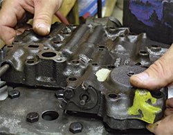
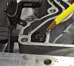
Two filters were used in the case under the separator plate. The filter shown here is in the governor feed passage. There is another larger filter or oil pump pressure screen. Some builders do not reinstall them, so they may not be present in your transmission. If present, remove them. Most rebuild kits come with new screens; if not, the old ones can be cleaned, blown dry with compressed air, and reused.
Step 4
The larger oil pump pressure screen or filter (if present) is located in a recess in the case toward the front.

Manual Shaft and Linkage Removal
Step 1
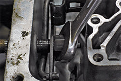
A spring or spacer is used to keep the transmission’s linkage in position in the case. Use a small screwdriver to remove it easily.
Step 2
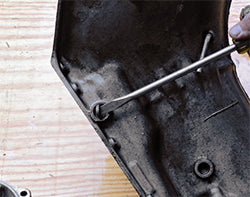
A large nut retains the shift linkage (rooster comb)to the manual shaft. Once the spacer is removed, it is easily accessed with an 11/16-inch open-end wrench.
Step 3
Two hardened Grade-8 bolts hold the parking pawl guide in the case. They do not need to be removed to get the linkage out. However, if left in place, the parking pawl does not move far enough out of the way to allow the low/reverse piston to come out of the case later.
Step 4
Remove these two bolts and remove the parking pawl guide from the case. Note that these two bolts are both Grade-8; keep them separate from other bolts, which may be softer Grade-5 material.
Step 5
The manual shaft can now be removed from the case. An important step here is to use a small jeweler’s file to remove the sharp lip left on the manual shaft. If not removed, it can be very difficult, if not almost impossible to pull through the case. Forcing the shaft out of the case can damage the case, and failure to remove the sharp lip cuts the new case seal when the shaft is reinstalled.
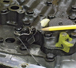
Step 6
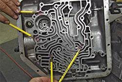
The check ball locations have been marked before removing them. Four steel check balls were used in the TH350 transmission. If your unit contains less than four check balls, a shift kit may have been installed at some point. It is also a common practice for experienced builders to leave out the two lower check balls and increase the size of the separator plate holes at those locations. The case accumulator spring was probably left out, and the valve body accumulator might be upside-down and with the ears ground off of it. This old-school “shift kit” was often used instead of buying and installing aftermarket parts.
1-2 Accumulator Removal
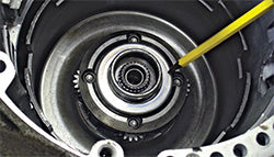
Step 1
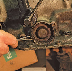
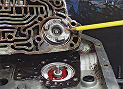
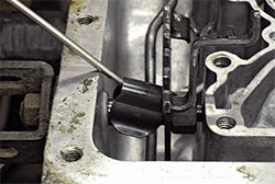
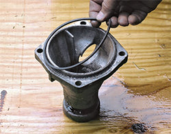
A small hole is in the case to allow for easy removal of the accumulator cover. Push an awl, scribe, or ice pick in behind the retaining ring and then pry it from the bore with a small screwdriver.
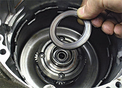
Step 2
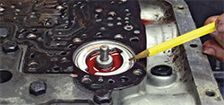
Once the retaining ring is out of the bore, remove the cover and O-ring. Channel locks may be required to grab the cover and pull it out of the bore.
Step 3
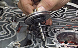
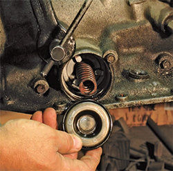
Remove the accumulator spring. This spring occasionally breaks and requires replacement.
Step 4
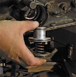
Remove the 1-2 accumulator from the case. Some units used metal rings; others used Teflon rings.

Vacuum Modulator and Modulator Valve Removal
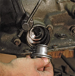
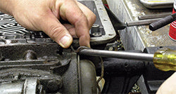
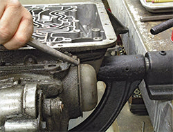
Step 1
The vacuum modulator is located on the rear passenger’s side of the case. It is held in place by a single 5/16-inch bolt and retaining clamp. Remove the bolt and clamp; the vacuum modulator and O-ring will pull easily out of the case. The valve can be pulled from the case with a small magnetic screwdriver. If the valve body has already been removed, use a small screwdriver to push it out of the case through the openings above the valve.
Step 2

Remove the modulator from the case and discard the O-ring. It’s not uncommon for the O-ring to stay in the case as it did here. Remove it with a small screwdriver or scribe.
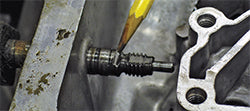
Step 3
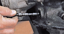
Remove the modulator valve from the case. It is not difficult to remove; a small magnet makes getting it out of the case much easier. Be careful not to drop or bend the valve. It must be free of nicks and burrs and move freely in the bore.
Oil Pump Removal
Step 1

Prior to removing the oil pump, it is a good idea to take an input shaft endplay reading. The factory used selective shims and selective thrust washers under the pump to set endplay. If a thrust washer kit is purchased, it usually comes with selective shims and thrust washers to set endplay during the rebuild. Endplay should be no more than .044 inch and no less than .010 inch.
Step 2

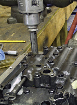
Remove the pump retaining bolts, which have 5/16-18 threads. At least two of the holes are threaded for 3/8-16 so slide hammers can be used to remove the oil pump.
Step 3
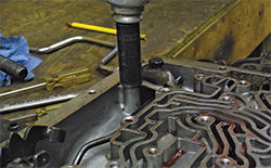
Using a slide hammer, shock the pump loose from the case. It is best to use two slide hammers and work back and forth between them.
Step 4
Then, lift the entire assembly off the case and set it aside for rebuilding later.
Intermediate Clutch Pack and Intermediate Band Removal
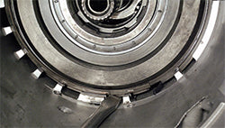
Step 1
Note that directly under the oil pump and on top of the intermediate frictions is a waved apply spacer. It provides a slight cushion to the clutch apply.

Step 2
Remove the intermediate clutches and frictions. A scribe or hook makes removing these components much easier.
Step 3
Remove the backing plate from the case. Note any wear or hot spots on the surface where the frictions apply.
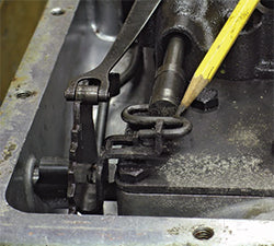
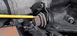
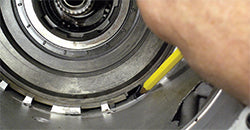
Step 4
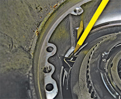
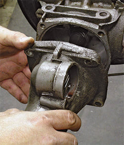
Locate the end of the band; note where it is cut out and engaged in the case lug.
Step 5

Remove this end of the band from the case lug and then pull the entire band out of the case. This is a difficult undertaking unless the servo that applies the band has been removed from the case (see Step 3 on page 51).
Forward/Direct Clutch Assemblies and Front Planetary Carrier Removal
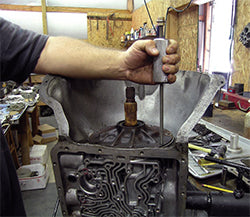
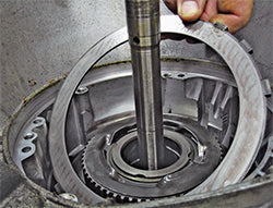
Step 1
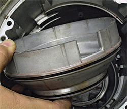
Get good purchase on the input shaft and lift the forward and direct clutch packs out of the case as an assembly. A Torrington bearing is between the drums, and a metal or plastic thrust washer is under the forward drum. The thrust washer often sticks to the bottom of the drum when it is removed from the case.
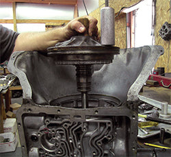
Step 2
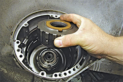
Remove the front planetary carrier and thrust washer from the planetary gear assembly. The thrust washer may be plastic or metal. Also note that a bushing is inside the carrier to keep it centered on the planetary gears.
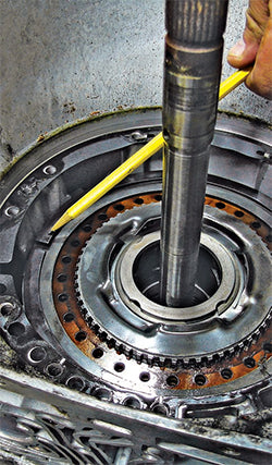
Step 3
Remove the thrust washer on top of the front planetary. This model uses a large Torrington bearing. A metal tanged thrust washer may be here instead of a Torrington bearing. They do not interchange during the rebuild without changing to a different style planetary gear that accommodates the tanged thrust washer.
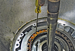
Step 4
Note the recess in the front planetary gear that accommodates the Torrington bearing. This surface is flat and, on some models, accepts a tanged thrust washer.

Governor Removal
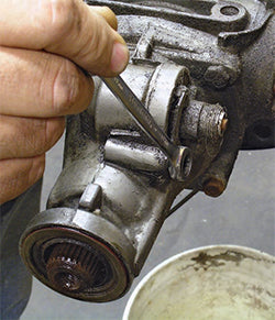
Step 1
The governor is under a cover on the rear driver’s side of the case. A retainer is used to secure the cover.
Step 2
Remove the retainer over the governor cover. It is in a blind hole on the upper end and snaps into a groove on the lower end.
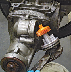
Step 3
Using a punch or large flat-blade screwdriver, drive the cover off of the transmission. Strike the cover as fl at as possible and in several different areas. Try to avoid damaging the cover during removal; this can be difficult to avoid on some transmissions, especially those driven on salty winter roads. The governor slides right out of the transmission. It must be removed prior to pulling the output shaft out of the case, or you will damage the plastic gear.

Tail Housing and Speedometer Gears Removal
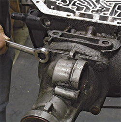
Step 1
Remove the bolt and retainer for the speedometer gear using a 1/2-inch wrench.
Step 2
Gently pull the speedometer gear housing from the tail housing. Take care not to damage the threads where the speedometer cable attaches.
Step 3
Loosen the four bolts that hold the tail housing in place. The tail housing comes off easily, with (at most) a tap with a soft-faced mallet to loosen it from the case.

Step 4
Slide the tail housing off the case and over the output shaft. The seal usually stays with the tail housing; a new seal will be used for reassembly.
Step 5
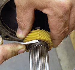
Use a small screwdriver to depress the end of the speed-ometer drive gear retainer. Slide the speedometer drive gear off the tail shaft. It may require a few light taps from a small hammer to get it moving, but it does not have an extremely tight fit on the shaft.
Step 6
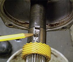
Turn the output shaft so the speedometer drive gear retainer is facing up. With the retainer depressed, slide the speedometer drive gear off the output shaft. It may require a few light taps with a small hammer to get it started. Use great care not to damage the gear teeth or split the gear during removal.
Front Planetary and Sun Gear Assembly Removal
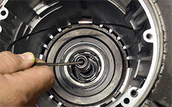
Step 1
Once the speedometer gear and retainer have been removed from the output shaft, move back to the front of the case. Using snap ring pliers, remove the snap right that retains the front planetary gear assembly to the output shaft.
Step 2
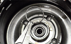
The snap ring that retains the output shaft to the front planetary can be difficult to remove. Use small snap ring pliers. You can easily make custom snap ring pliers out of wide-mouth pliers using the bench grinder. Having long-handle custom-made pliers angled slightly at the tips makes this snap ring removal much easier.
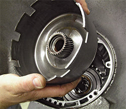
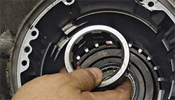
Step 3
Slide the planetary assembly off the output shaft. Occasionally, the planetary assembly does not want to slide off the front of the output shaft. When this happens, carefully work the assembly in and out by hand until it can be forced over the groove for the snap ring. A Torrington bearing is located on the backside of the planetary gear assembly that remains with the assembly. No plastic or metal thrust washer is used against the sun gear.
Step 4

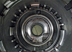
Once you lift the front planetary out of the way you can see the sun gear. Note that no bushing or thrust washer is present. Instead, a trapped Torrington bearing is inside the front planetary. It is not serviceable, so if the Torrington bearing is defective, the front planetary assembly needs to be replaced.
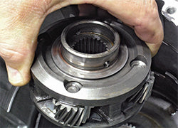
Step 5
Lift the sun shell out of the case; it should slide off with little effort.
Step 6
The thrust washer under the sun shell may be either plastic or metal. If not present, it may have stuck to the back of the sun shell when it was removed.
Center Support and Low/Reverse Roller Clutch Assembly Removal
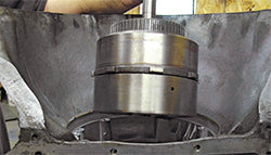
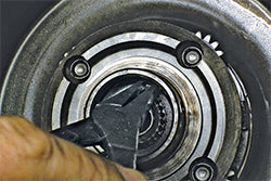
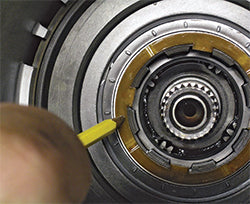
Step 1
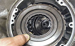
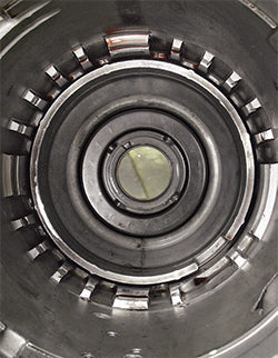
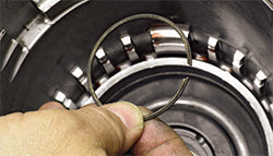
The center support must be removed next. Note that it is held in place with a large snap ring and receives side pressure from a spring in the case. This spring is often referred to as an “anti-clunk” spring.
Step 2
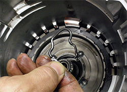
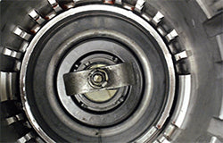
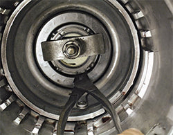
Use a wide flat-blade screwdriver to pry the free end of the center-support retaining ring inboard far enough to clear the case lugs (as shown).
Step 3
Once the snap ring clears the case lugs reach in with your free hand to pull it right out of the case.
Step 4
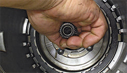
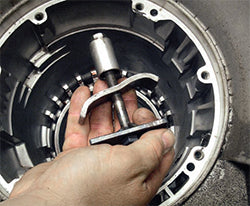
Pull out the low/reverse sprag inner race. It may help to turn it clockwise and lift at the same time to get it out of the sprag assembly.
Step 5
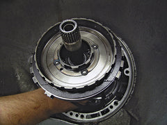
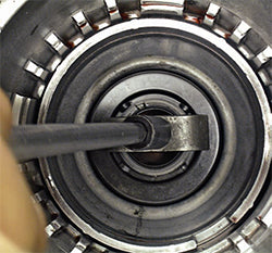
Remove the center support assembly from the case. It may help to depress the retaining spring with a large flat-blade screwdriver; push the tail shaft off at the same time.
Step 6
Don’t forget about the retaining spring, it may fall out of its position during the removal of the center support.
This tech tip is from the full book, GM TURBO 350 TRANSMISSIONS: HOW TO REBUILD & MODIFY.
For a comprehensive guide on this entire subject you can visit this link: LEARN MORE ABOUT THIS BOOK HERE
SHARE THIS ARTICLE: Please feel free to share this post on Facebook Groups or Forums/Blogs you read. You can use the social sharing buttons to the left, or copy and paste the website link: https://www.cartechbooks.com/blogs/techtips/gm-th350-transmission-disassembly-guide
Output Shaft and Low/Reverse Clutch Pack Removal
Step 1
Once the center support is removed, grasp the output shaft firmly and pull it from the case. Low/Reverse Apply Piston Removal
Step 2
The low-planetary assembly and the low/reverse steels and frictions come out with it. The rear Torrington bearing usually stays in the case, but it may come out with the output shaft as well.
Low/Reverse Apply Piston Removal
Step 1
The last items to remove from the case are the low/reverse piston, spring cage, and snap ring.
Step 2
This low/reverse spring compressor is a very simple homemade tool. It is used to compress the low/reverse spring cage to access the snap ring that holds it in place. This tool is available as an aftermarket item. However, it is very easy to make from a piece of hardened all-thread or a long threaded bolt, a socket, a nut, and a couple of pieces of fl at stock. (See Pic 1-20).
Step 3
Center the spring compressor in the bore of the case so that both arms distribute the load evenly to the spring cage. Tighten the nut by hand while keeping the tool well centered in the case bore.
Step 4
Using a ratchet and long extension, tighten the spring compressor just enough to release pressure on the snap ring.
Step 5
Using snap ring pliers, locate the free ends of the snap ring and expand it. Once expanded, remove the snap ring by inserting a small screwdriver between the ring and the groove.
Step 6

Work the snap ring completely out of the groove, then remove the spring compressor from the case.
Step 7
Once the spring compressor is out of the way, you can remove the snap ring.
Step 8
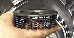
Remove the spring cage from the case. A later-model spring cage is shown with the springs attached to the cage.
Step 9
Apply air pressure to the oil feed hole in the case to remove the low/reverse piston from the case. Tilt the transmission upward slightly during this procedure to keep the piston from coming out of the case and rolling out onto the shop floor.
Step 10
Lift the apply piston out of the case. Note that it has a notch in it to clear the parking pawl. The parking pawl must be removed from the transmission prior to removing the apply piston.
Case Cleaning and Rebuilding Preparation
Step 1
The case is now empty and ready to be cleaned and inspected. Look specifically for case lug damage at the center support area and for cracks in the bellhousing area. Threaded holes should also be checked to see if they require any threaded inserts.
Step 2
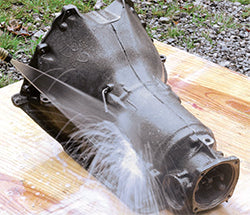
A high-pressure power washer is an excellent way to remove heavy grease, dirt, and road tar from the case.
Step 3
Use a large flat-blade screwdriver or seal puller to remove the manual shaft seal from the case.
Step 4
Power wash the tail housing as well and remove the seal if it is still in place.
Step 5
Dry the case with compressed air, taking extra time to get all of the water out of the many case passages. Once the case is cleaned and dry, the exterior can be painted. Cast-finish paint looks very much like the factory finish.

Written by Cliff Ruggles and posted with permission of CarTech Books
This tech tip is from the full book, GM TURBO 350 TRANSMISSIONS: HOW TO REBUILD & MODIFY.
For a comprehensive guide on this entire subject you can visit this link: LEARN MORE ABOUT THIS BOOK HERE
SHARE THIS ARTICLE: Please feel free to share this post on Facebook Groups or Forums/Blogs you read. You can use the social sharing buttons to the left, or copy and paste the website link: https://www.cartechbooks.com/blogs/techtips/gm-th350-transmission-disassembly-guide