
Rebuilding an AOD, AODE, or 4R70W has always been perceived as a task for professionals only. And for the most part, it is best left to them, especially if you lack the confidence necessary to do it yourself. However, if you really want to understand automatic transmission function, you can perform the rebuild at home. Follow this book carefully, pay close attention to all the details, and you can achieve great success rebuilding your Ford AOD. The key here is to take sharp, well-focused images and liberal notes during each phase of disassembly.

FORD AOD TRANSMISSIONS: REBUILDING AND MODIFYING THE AOD, AODE AND 4R70W
For a comprehensive guide on this entire subject you can visit this link:
SHARE THIS ARTICLE: Please feel free to share this article on Facebook, in Forums, or with any Clubs you participate in. You can copy and paste this link to share: http://www.cartechbooks.com/techtips/how-to-disassemble-ford-aod-transmissions/
Why Transmissions Fail
Disassembly is a forensics study to learn why a transmission failed and how to prevent failure from happening again. Some transmission rebuilds are nothing more than attending to wear and tear. However, most are failure related.
In general, not enough attention is paid to regular preventative maintenance: fluid and filter changes. Automatic transmissions, regardless of automakers’ claims of “life of the unit” service intervals, require regular fluid and filter changes every 30,000 miles for maximum longevity. Yet most motorists never give it a thought until they’re on the road-side, waiting for a flatbed.

Fundamentally, the AOD is a simple automatic because it employs the same basic core as the cast-iron FMX with its Ravigneaux compound planetaries. The main difference is the addition of an overdrive system and throttle valve modulation.
Clean, plentiful lubrication is crucial to long life. Clean lubrication provides a good oil wedge between moving parts and good hydraulic line pressure via healthy seals and clutch discs. Clutch and band frictions saturated with plenty of fluid go the distance and provide durability.
There’s a long-standing belief that if a transmission has never been serviced it is best to leave well enough alone and let it run its course until failure or a rebuild. Most transmission professionals have indicated that fresh fluid tends to shock old seals, leading to pressure loss and failure. These same professionals also say that transmission failure can depend upon how abused the transmission has been along the way. Towing and competition cause heat damage to seals and clutches. If your transmission has passed the 100,000-mile mark in normal operation without a fluid change, it is best to leave well enough alone until it requires a rebuild.
Burned Clutches and Bands
Brian Fortune of Tom’s Transmissions suggests that as you disassemble an AOD, AODE, or 4R70W, it is important to first determine failure origin. Failure isn’t always the first thing you see; it may be something seemingly unrelated that indirectly caused the failure. This could be a loss of line pressure from a worn seal, a sticking pressure relief valve, or dirty fluid, any of which may explain why clutches and bands burned up. Clutches and bands burn due to slip-page and no other reason, aside from fluid starvation.
Transmission failure is normally a chain reaction, according to Brian; a series of small issues and disruptions that lead to failure. The normal pattern of failure is seal wear or damage, which leads to loss of hydraulic pressure and clutch and band slip-page. This in turn contaminates the fluid with friction material, cutting seals and further hindering control pressure, causing slippage and burned clutch and band frictions.
Poor Assembly
Transmissions also fail due to poor assembly technique in transmission shops, according to Mike Stewart of Mike’s Transmission. Whether it is the mass rebuilder or an independent repair shop, he believes that many things are overlooked in the course of a transmission rebuild.
During teardown, you want to study wear patterns and anything else that appears out of the ordinary. Look for parts that don’t work well together. Just because the transmission functioned doesn’t mean it was assembled properly. Mass rebuilders, for example, toss thousands of parts in bins with other seemingly like parts, clean them up, machine or replace as necessary, and put transmissions together haphazardly. The result is different generations of transmission parts thrown together that aren’t always engineered to work well together.

Factory Engineering Changes
Ford is notorious for making engineering changes, and dozens of them occur over the production life of a transmission design. This means you must pay very close attention to parts intended to work together as well as parts that were never designed to be together. The AOD, for example, had significant changes throughout its production life, which means you can wind up with parts that don’t even fit, let alone work well together. Teardown teaches us what went wrong with a transmission: it also provides the opportunity to learn how it should go back together. Take plenty of pictures and liberal notes as you go along. When something just doesn’t look right, take note of it and don’t be afraid to ask questions.
Begin Disassembly
Step 1: Remove Pan and Filter
Disassembly begins with removing the pan and filter. The pan has 14 bolts and the filter has three. The first order of business is to examine the remaining transmission fluid in the sump. If it’s brown to black in color, this indicates badly burned friction bands and clutches, which normally happens due to a loss of control pressure. Insufficient pressure causes clutch and band slippage and the corresponding heat.
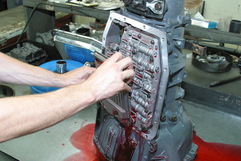
Step 2: Unbolt Valve Body

Remove the valve body using a 10-mm socket; it should be completely disassembled for cleaning. Use a digital camera to record how it comes apart. Closely examine all moving parts (valves and balls) for damage/scoring.
Step 3: Remove Valve Body

Carefully remove the valve body and lay it on the bench with the separator plate facing up. Because there are ball check valves throughout the valve body, it must be fl at on the bench to avoid losing these critical parts.
Step 4: Examine Manual and Throttle Valves

The manual and throttle valve mechanisms are exposed once you remove the valve body. The manual/throttle valve linkage is a shaft within a hollow shaft configuration. The manual shaft is hollow, and the throttle valve shaft is solid within the manual shaft.
Tailshaft, Servos and Pistons Removal
Step1: Remove Tailshaft Housing

When removing the tailshaft housing pay attention to the seal and bushing condition. Both must be replaced in the course of a rebuild. Go with a new bushing, seal, and slip yoke. This is a transmission shop with work-bench drains. At home, you need to have completely drained the transmission or you will have a huge mess. Make sure the transmission is completely drained first.
Step 2: Remove Overdrive Band Servo

Remove the overdrive band servo cover and piston assembly using a common screwdriver to get at the snap ring. This snap ring can be tricky to remove. You may also use two small common screwdrivers or an awl for snap-ring removal.
Step 3: Inspect Overdrive Band Servo Piston (Critical Inspection)

Remove the overdrive cover/piston assembly and take a close look at seals and the bore for scoring. Seal and/or bore damage is caused by fluid contamination. Fluid contamination can be caused by clutch/band friction material, which only gets worse with time and slippage. Scoring can be honed out of the bore. Piston scoring calls for replacement.
Step 4: Remove Low-Reverse Servo Cover

The low-reverse servo cover assembly is next. Using a common screw-driver, remove the snap ring. Push on the cover/piston with a hammer handle or your thumb to relieve the pressure on the snap ring.
Step 5: Remove Low-Reverse Servo Piston

This is the low-reverse servo cover and snap ring. The piston and return ring are inside the low-reverse servo bore. Inspect the piston seal and bore for damage, especially if there’s fluid contamination.
Step 6: Remove 2-3 Shift Accumulator

The 2-3 accumulator cover (next to the low-reverse servo) is next, with snap-ring removal. Again, look for signs of leakage and bore damage issues.
Step 7: Inspect 2-3 Shift Accumulator Piston

The 2-3 accumulator piston has two seals. Inspect the seal and bore condition. Any scoring or seal damage is a clue to what may have happened to control pressure.
FORD AOD TRANSMISSIONS: REBUILDING AND MODIFYING THE AOD, AODE AND 4R70W
For a comprehensive guide on this entire subject you can visit this link:
SHARE THIS ARTICLE: Please feel free to share this article on Facebook, in Forums, or with any Clubs you participate in. You can copy and paste this link to share: http://www.cartechbooks.com/techtips/how-to-disassemble-ford-aod-transmissions/
Front Pump Removal and Disassembly
Step 1: Pull Front Pump Assembly

Using a puller, remove the front pump assembly, which is iron in the AOD and aluminum in the AODE and 4R70W. Not all applications require a puller. But count on needing one to get the pump out.
Step 2: Inspect Front Pump Assembly

The AOD front pump assembly also includes the intermediate clutch piston and spring retainer assembly. The spring retainer returns the inter-mediate clutch piston to rest when pressure is released. The intermediate clutch pack is at the front of the case.
Step 3: Remove Intermediate Clutch Piston

Remove the intermediate clutch piston from the pump housing, which is also the clutch cylinder. Inspect the seal and bore for scoring and damage. The three domes (or bumps) in each of the three sections are return spring mounts.
Step 4: Disassemble Front Pump

Split the front pump housing by removing the five fine-thread bolts with a 10-mm socket. This is also the intermediate clutch cylinder sans piston.
Step 5: Inspect Front Pump Cavity

With the front pump opened up, the AOD’s gear pump main cavity is ready for inspection. Before removing the rotating assembly, examine the inner and outer gears for unusual wear patterns and scoring. Also inspect the pump cavity walls for scoring.
Internal Components Removal and Inspection
Step 1: Pull Forward Rotating Assembly

With the pump removed, the input shaft, intermediate clutch, one-way clutch, reverse clutch, and forward clutch come out as an assembly.
Step 2: Inspect Low-Reverse Drum

This is the intermediate clutch pressure plate and forward rotating assembly just removed from the main case. Examine the low-reverse clutch drum (also known as the overdrive drum) for excessive wear and tear. Make plans now to go with the wider Lincoln drum and overdrive band.
Step 3: Examine Intermediate Clutches and Plates

Inspect the intermediate clutches and clutch plates for abnormal wear patterns. As with any rebuild, replace the clutch discs and dress the steel plates. Check the steel plates for heat cracking and discoloring.
Step 4: Separate Low-Reverse Clutch from Forward Clutch

Separate the low-reverse clutch drum from the forward clutch. Check the clutch hubs for scoring and damage. Look for atypical wear patterns, such as shiny spots and nicks that can snag clutches. Normal wear patterns are uniform in nature.
Step 5: Examine Low-Reverse Clutches

Give the low-reverse clutch discs and steel plates a close look for excessive and unusual wear such as general discoloration, hot spots, and cracking. These clutch discs and plates look good and can be returned to service. However, the clutch plates should always be replaced. The steel plates can be resurfaced.
Step 6: Check Wear Patterns (Critical Inspection)

Inspect the low-reverse clutch shim for abnormal wear. There doesn’t appear to be any unusual wear patterns here, which means the shim can be returned to service.
Step 7: Remove Clutch Hub

Remove the intermediate clutch hub from the low-reverse clutch pack. Inspect it closely for wear and damage. The clutch hub teeth must be smooth so clutch frictions can move freely.
Step 8: Inspect Low-Reverse One-Way Clutch

This is the low-reverse drum’s one-way roller clutch, which allows rotation one way, but not the other. Rollers and springs should be free of damage and missing parts. If there’s any doubt, or even minor scoring, replace the one-way clutch.
Step 9: Examine Low-Reverse Drum

This is the low-reverse drum in a disassembled state, revealing the wavy Belleville spring inside the clutch drum, which releases this clutch pack. The interior clutch disc teeth should be free of scoring and any irregularity that would hinder clutch movement.
Step 10: Disassemble Forward Clutch

Disassemble the forward clutch, including the Torrington bearing and clutch hub. Inspect the teeth for scoring and any damage that can hinder clutch friction movement.
Step 11: Remove Overdrive Band

With the low-reverse drum and forward clutch removed, the overdrive band is next. To make your AOD the best it can be in terms of durability, opt for the wider 2-inch Lincoln overdrive band and corresponding drum for greater hookup. Never reuse the overdrive band.
Step 12: Inspect Forward Clutch Hub

Inspect the forward clutch hub for irregularities that can cause clutch friction issues. The teeth should be free of scoring that can hinder clutch movement.
Step 13: Remove Drive Shell and Sun Gear

Remove the drive shell and forward sun gear, again with close inspection of gear teeth for abnormal wear patterns. Look at the shell’s central hub and check for cracks.
Step 14: Remove Center Support and Planet Carrier

Remove the center support and planet carrier. Pay close attention to the anti-clunk spring during this phase of disassembly as it’s easy to overlook.
Step 15: Inspect Planet Carrier (Documentation Required)

Disassemble and inspect the planet carrier. The planet gears should spin freely and be free of side play (wobble). Any resistance or binding is cause for rejection. This is the planet carrier’s one-way roller clutch assembly. It should be replaced, but if you feel compelled to reuse it, inspect all of the rollers and springs. Note the assembly position for proper installation of rollers and springs.
Step 16: Remove Low-Reverse Band

Remove the low-reverse band. The low-reverse band, which is cast iron with a friction surface, doesn’t work as hard as the over-drive band and as a rule rarely has to be replaced. Regardless, it’s always a good idea to start with a fresh low-reverse band to minimize the risk of failure, especially on a high-mileage transmission.
Disassembly
The proper path to take during transmission teardown begins with draining and appropriately recycling fluid and worn parts. Remove the pan first and examine the sump for contaminated fluid. Pink fluid indicates stability and proper operation. Burned fluid results from high operating temperatures; a lot of friction material in the fluid indicates clutch and band slippage.
Geartrain Removal
Once the pan is removed and you have access to the valve body, keep close track of bolt size and length during valve body removal. With the valve body removed, you have access to servo pistons, the accumulator, manual and throttle valve linkages, and the parking pawl. Before disassembling the linkages, take pictures and notes.
FORD AOD TRANSMISSIONS: REBUILDING AND MODIFYING THE AOD, AODE AND 4R70W
For a comprehensive guide on this entire subject you can visit this link:
SHARE THIS ARTICLE: Please feel free to share this article on Facebook, in Forums, or with any Clubs you participate in. You can copy and paste this link to share: http://www.cartechbooks.com/techtips/how-to-disassemble-ford-aod-transmissions/
Tailshaft housing removal reveals the governor on AOD models. (AODE and 4R70W models do not have a governor.) Governor disassembly requires great care and is something that needs to be done separately because disassembly and assembly are performed all in one process. Lay the governor out as assembled and take pictures just in case. Governors are calibrated based on vehicle type and load.
Servos and accumulators (2-3 and 3-4), which are retained with snap rings and covers, are removed next. Not all AOD units have the 3-4 shift accumulator, which was discontinued in 1989. The over-drive band servo has a snap ring, cast-aluminum cover, and piston. The low-reverse servo has a snap ring, steel cover, and piston. As you remove these assemblies, examine the seals for damage and the hard parts for scoring. Check the springs for integrity. If there’s any doubt, replace the spring.


When the servos have been removed from the case, this frees up the geartrain. The front pump is removed using a puller because it is such a tight fit. An AOD uses a cast-iron pump and stator support; because iron and aluminum are dissimilar metals, this combination can prove challenging. The AODE and 4R70W pumps are aluminum, which tend to be easier to remove by hand. Never beat the pump/stator with a hammer. Gently pry where you can. If the pump proves to be stubborn, use a puller. You can also use a slide hammer, which is easier to find at a rental outlet.
After you have removed the pump and inner overdrive input shaft, the geartrain slides out in segments. First to come out is the intermediate clutch pack, one-way clutch, forward clutch, and hub. Carefully remove the overdrive band and examine the friction material for wear and tear. It should be replaced regardless of condition. Turn the overdrive band to get it off the anchor pin and remove. Next comes the sun gear and number-5 Torrington (thrust) bearing.
With the forwardmost portion of the geartrain out, next is the support assembly, which is locked in place with a large snap ring and buffered with anti-clunk springs. Pay close attention to how the support assembly is positioned. The support assembly comes out with the planet carrier. Remember to take pictures as you go. Next, remove the low-reverse band.
Next in line are the direct clutch, steels, and frictions, which are tied to the output shaft. Because the governor has already been removed, the output shaft should slide out through the front of the transmission case. With all rotational assemblies removed, you will see the number-9 Torrington (thrust) bearing, which is removed at this time.
Governor and Output Shaft Removal
Step 1: Remove Governor Assembly

To remove the governor valve remove the C-clip. Governors are calibrated for vehicle type and weight by spring pres-sure. If your AOD is being installed into the same vehicle that it originally came from (or a similar vehicle), you should have few concerns about governor calibration.
However, if your AOD core is from an unknown vehicle, it would be wise to calibrate the governor to your application, using the spring combination shown in the Ford Master Parts Catalog for your particular vehicle type. The governor controls are based on output shaft speed, which controls line pressure.
Step 2: Remove Governor Drive Ball

The governor valve is driven by the output shaft and this ball, which acts like a Woodruff key. Do not lose this ball. Keep it in a safe place for reassembly.
Step 3: Remove Direct Clutch and Output Shaft

Completely disassemble the direct clutch and output shaft package, right down to where the outputshaft joins the direct clutch. Debris can become trapped in the clutch drum and contaminate the fluid.
Step 4: Disassemble Direct Clutch and Output Shaft

Disassembling the direct clutch and output shaft exposes the number-8 Torrington thrust bearing. All cast-iron and Teflon shaft seals should be removed, taking note of their positions and the type of seal.
Step 5: Inspect Direct Clutch

Disassemble the direct clutch to reveal clutches and steels. Inspect the clutch discs and plates for heat issues and scoring. As has been stressed earlier, clutch discs must be replaced and the plates inspected for heat damage and wear.
Step 6: Inspect and Resurface Plates

These clutch discs and plates look healthy, although the plates could use some help. When the plates are shiny, they can be resurfaced to a healthy crosshatch pattern for good clutch hookup.
Subassembly Removal
With the geartrain removed, the subassemblies must be disassembled. The reverse clutch pack (also known as the overdrive drum) and forward clutch are disassembled next. Keep track of the number of clutches and steels in each of the clutch packs. As clutches and steels come out, inspect both for abnormal wear. Any bluing in the steels is cause for rejection and further investigation to learn why they became hot.
Most transmission rebuild kits come with fresh steels and clutches, which means you won’t be using the originals. If you’re going to reuse steels, reface them with a very fine abrasive in a swirling motion to promote good clutch hookup. You do not want shiny clutch steels, but instead rough surfaces for better engagement.
While you have the geartrain disassembled, inspect the one-way clutch (reverse clutch drum) for smooth, consistent operation. It should turn smoothly in one direction, but lock up in the opposite. Any inconsistencies are cause for rejection and replacement.
Each clutch drum has an apply piston, which engages the clutches and steels. Pistons are generally removed with compressed air. When doing this, turn the clutch drum down, away from your face, and pop the piston toward the workbench and a soft towel to prevent damage. Inspect the inner and outer piston seals for damage that may have caused transmission malfunction.
Each clutch pack must be carefully inspected for areas that can cause clutch frictions and steels to hang up. Ragged edges and scored surfaces should be checked with clutches and steels in place to see how these segments function. If they hang up, dress the irregular surface or replace the drum.
The front pump assembly is also the intermediate clutch cylinder and piston, which is disassembled, cleaned, and inspected. Look for irregularities such as unusual wear, ragged edges, and scoring that can damage clutch piston seals. Make sure all return springs are present and serviceable.
When you split the pump for a look inside, be sure to note how the inner and outer pump gears are configured and carefully remove them for inspection. They must go back in exactly as they came out. Examine the surfaces for scoring and excessive wear. If wear is excessive, replace the pump. You can always replace the gears. If they are worn, however, chances are very good that the pump cavity is also excessively worn.
As you disassemble the clutch drums and other subassemblies, make sure you have removed all seals and bearings/thrusts. Seals, especially, are easy to overlook when they must be replaced.
Soft Parts Replacement
Step 1: Perform a Thorough Cleaning

All transmission hard parts go into a parts washer. Make sure all small parts have been accounted for. When these items come out, dry them with compressed air, which should be blasted into all passages.
Step 2: Replace Broken Belleville Spring

This low-reverse clutch pack has a cracked Belleville spring, which must be replaced. This is a stress crack due to metal cyclic fatigue. Belleville springs work in a fashion called “oil canning.” In time, the metal weakens and cracks due to duty cycling back and forth as pressure is applied to the clutch piston. Play it safe and replace all Belleville springs during a rebuild.
Step 3: Replace Overdrive Band

Here’s another look at a burned overdrive band with heat cracking in the friction. Regardless of the condition, overdrive bands must always be replaced and the drum dressed for good hookup without slippage.
Step 4: Inspect Low-Reverse Band

The low-reverse band is different from the overdrive band; it’s cast iron with friction material instead of steel. The low-reverse band isn’t subjected to as much stress as the overdrive band and lasts considerably longer. Replacement is suggested in any case.
Step 5: Use C-Clamps for Clutch Disassembly

Although transmission shops often have clutch spring compressors for piston and clutch removal, you can do this at home with C-clamps. Be sure to always use eye and face protection.
Step 6: Remove All Seals

With each clutch drum disassembly, make sure you remove all the seals and take note of the seal type and location during disassembly. Installing seals backward and in the wrong location is common and can cost you plenty in terms of time and money.
Step 7: Replace All Seals

Some piston seals are well hidden, which means you need to examine every square inch of a clutch piston and drum during disassembly to make sure all seals have been removed. Not all seals are neoprene. Some are iron, Teflon, and other synthetics. They must all be replaced.
Written by George Reid and Posted with Permission of CarTechBooks
