
Selecting the correct hypoid gears for your vehicle and application is essential for attaining maximum performance. The gears are shaped as a revolved hyperboloid, which means that the pitch surface of the gear itself is a hyperbolic surface. Hypoid gears are centered off-axis, where the pinion gear sits lower than the centerline of the ring gear, allowing the pinion gear to be larger than it would be if it were on-center. Because of the size and spiral angle of the pinion gear, hypoids engage multiple teeth at once, so they can handle higher torque loads.
This tech tip is from the full book, CHEVY DIFFERENTIALS: HOW TO REBUILD THE 10- AND 12-BOLT.
For a comprehensive guide on this entire subject you can visit this link: LEARN MORE ABOUT THIS BOOK HERE
SHARE THIS ARTICLE: Please feel free to share this post on Facebook Groups or Forums/Blogs you read. You can use the social sharing buttons to the left, or copy and paste the website link: https://www.cartechbooks.com/blogs/techtips/how-to-rebuild-gears-in-chevy-and-gm-differentials-step-by-step
One of the side effects of the hypoid design is a sliding action of the gear teeth as they rotate. This is where a lot of issues appear. As the teeth slide along each other, the friction generates heat, which is the enemy of gears. If a differential runs low on gear oil for even a short time it results in serious damage so that it is unrepairable; you have to replace the gears.

Ring gears convert the engine’s rotation into forward motion, but there is more to selecting a gear set than just what size you think you need.
The gears must be arranged in a very specific position relative to each other, within a couple of thousandths of mesh. This is expressed numerically as .002 inch, which is similar to the bearing clearances in the rotating assembly of an engine. The problem is that while it is easy to measure the clearance between a crankshaft journal and a rod, doing the same on a ring gear set is much more difficult. See Chapter 7 for more details.
Determine Gear Ratio
Determining the ratio of gears installed inside your housing is simple. You need to count the rotations of the tires and the driveshaft at the same time. It is easiest with a helper, but you can do it alone with some preparation. First, you need a floor jack, jackstands, tape or a grease marker, as well as paper and a pen.
Jack the vehicle up until the wheels are suspended. Secure the jackstands under the vehicle and rest the weight of the car on the stands. (Never work under a car with just a floor jack. If the floor jack fails, you can be severely injured.) Place a piece of tape from the fender to the tire or to the ground and to the tire along the sidewall. This is the rotational marker. Place another piece of tape from the driveshaft to the housing. This is the driveshaft marker. If you are working by yourself, you can put the tire marker on the inside of the tire so you can see it from under the car.

A sizing code is stamped on every pinion shaft. Gears are built as a matched set, and they cannot be interchanged.

The number of teeth is stamped on each gear. The small number is the pinion gear tooth count; the large number is the ring gear tooth count. You divide the big number by the little number to get the ratio. Here, 40 ÷ 13 = 3.076, so these are 3.08:1 gears.

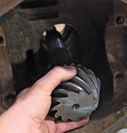
This 3.73:1 ring gear fits the GM 12-bolt passenger car carrier. The gear measures 8.8 inches, which is noted in the part code: GM8.8-373.
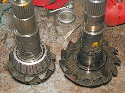
To change gear ratios, you need different pinion gear sizes. This pinion gear (left) is a 4.11, and the gear (right) is a 3.08. This is part of the reason that different carriers are required for certain gear ranges. The bigger the gear ratio, the farther away the pinion gear sits. The carrier repositions the ring gear to compensate.
Put the transmission in neutral. Next, rotate the driveshaft and count the number of complete rotations until the tire has made one full revolution. It is unlikely that the drive-shaft rotations will be equal, so you can approximate the number for a street vehicle. About 3/4 of a turn gets you close to .73 to .80. This is good enough for street vehicles.
If you need a more precise indication of the gear ratio, open the housing and read the numbers stamped into the each gear. If you can’t read the numbers, simply count the teeth and use the following formula:
Gear Ratio = ring teeth ÷ pinion teeth
For example, a vehicle with 39 ring teeth and 11 pinion teeth has a 3.54:1 gear ratio (39 ÷ 11). The gears’ purpose is to transfer power from the engine to the wheels, and the differential does this by torque multiplication. If an engine were directly connected to the wheels, the vehicle would struggle to move. The enormous size and resistance of the wheel would overload the engine and bog it down. The vehicle would take a long time to actually move.
During acceleration, the engine is spinning from idle (650 to 1,000 rpm) to the 5,000-rpm range for normal street driving. Forward motion begins almost instantly without reducing the engine’s speed. This is because of torque multiplication: As torque increases, the speed of rotation decreases. The basic formulas are:
Ring Gear Torque = input torque x axle ratio
Ring Gear Speed = input speed ÷ axle ratio
For example, a stock LS1 engine sends 345 ft-lbs of torque to a rear differential with 3.73:1 gears at 4,400 rpm. An engine that produces 345 ft-lbs certainly has respectable torque, but it is simply not enough to get a 4,000-pound vehicle moving.
You can test this on a vehicle with a manual transmission. Start out in first gear, and the vehicle takes off like normal; start off in fourth, and the engine bogs down and dies. This is because it takes tremendous torque to generate forward motion. Using the formulas you get 1,287 ft-lbs of torque (345 x 3.73) and 1,180 rpm (4,400 ÷ 3.73).
As a result of these increases, the mechanical advantage of the drive-train as a whole has increased. How-ever, the axle assembly is only one component of the drivetrain; and there is always a second set of gears in the drivetrain: the transmission.
To get the complete picture, you need the vehicle’s gearing. For example, an LS1 transmission with 350 hp and 345 ft-lbs of torque, is a Tremec T56 6-speed with the following gearing numbers:
First 2.97
Second 2.07
Third 1.43
Fourth 1.00
Fifth .84
Sixth .56
As an example, the rear differential is fitted with 3.73:1 gears. Using the formula, the final torque output at peak RPM in first gear is 3,822 ft-lbs (345 x 2.97 x 3.73). Total RPM is 397 (4,400 ÷ 2.97 ÷ 3.73).
This means that by the time the engine is spinning at 4,400 rpm, the axles are seeing 3,822 ft-lbs of rotational torque, spinning just 397 times per minute. This would certainly get a 4,000-pound car moving down the road.
Shift the transmission into fourth, and the gearing of the transmission is 1:1, so the torque and RPM of the transmission is exactly the same as the engine (minus a little bit for parasitic loss). The first calculation determines the torque needed from the gears, just 1,287 ft-lbs, to move the car.
An object in motion tends to stay in motion. Once the vehicle is in motion, the torque required to keep it in motion is drastically reduced, and when the vehicle is in motion, horsepower takes over. Torque gets the vehicle moving and horsepower keeps it moving at speed. Consider the example vehicle in sixth gear; plugging the data into the formulas you get 721 ft-lbs of final torque (345 x .56 x 3.73) at 4,400 rpm and 165 rpm (345 ÷ .56 ÷ 3.73). There is very little output in terms of torque and rotational speed, yet the vehicle would be traveling at a very high rate of speed.
This is important because there are trade-offs for gear ratios and the way they relate to vehicle acceleration (quickness) and overall speed (speed). For a gear to achieve more mechanical advantage (numerically higher ratio), the pinion gear has to become smaller. Not only does this make the gear weaker, it also limits the top speed of the vehicle.
This tech tip is from the full book, CHEVY DIFFERENTIALS: HOW TO REBUILD THE 10- AND 12-BOLT.
For a comprehensive guide on this entire subject you can visit this link: LEARN MORE ABOUT THIS BOOK HERE
SHARE THIS ARTICLE: Please feel free to share this post on Facebook Groups or Forums/Blogs you read. You can use the social sharing buttons to the left, or copy and paste the website link: https://www.cartechbooks.com/blogs/techtips/how-to-rebuild-gears-in-chevy-and-gm-differentials-step-by-step
Gear Selection
A variety of terms can be used to describe gear type, such as “short,” “deep,” “tall,” or “highway.” These terms typically lead to confusion even for an experienced car owner/mechanic. Short gears are numerically higher, such as 3.73:1 or 4.11:1 ratios. These are the deep gears that get the vehicle moving quickly due to their high ratio of input to output rotations.
Tall or highway gears are the low-number ratios that yield high speed and efficiency, such as 2.80:1 or 3.08:1. These gears do not provide the torque multiplication rates that the larger ratios provide. Once the vehicle is up to speed, they allow the engine to spin more slowly, which means they are more efficient for highway use.
Finding the ratio is simple. For every rotation of the ring gear, the pinion gear rotates “X.XX” times. For example, a 3.73:1 gear set requires 3.73 turns of the pinion gear to spin the ring gear one full rotation. This is a direct correlation of the driveshaft rotation to the axle rotation. The lower the number, the faster the axles spin in relation to the engine. This is why lower gears are efficient; the engine doesn’t have to spin as fast to keep the car moving and can reach higher speed, but it is much harder to get the car going than with larger numerical gears.
Choosing the gear ratio for your vehicle can be difficult. You have to find the balance between top speed and quickness for your application. Specific applications, such as drag racers and off-road rock crawlers need deep gears to get the vehicle moving quickly or maximize engine torque output at low speeds. High-speed racing, such as with circle track cars, needs top-end speed, so the takeoff speed is not much of a factor.
Street vehicles, however, must strike a fine balance between the two, and that means factoring in several key components such as intended use, transmission type and gearing, and tires.
Intended Use
This is the single most important component for gear selection. If you are building a stoplight-to-stoplight street machine, higher numerical gears are certainly applicable. If the vehicle sees a lot of highway miles, steep gears drastically reduce the overall speed of the vehicle and make the engine spin much faster.
Transmission Type and Gearing
The following gear ratio setup is one of the greatest upgrades for a transmission overdrive. It does the opposite of the lower gears; it makes the output shaft spin faster than the engine itself. This means that the rear gears have more input speed to work with. A 1:1 transmission with output running to a 3.73:1 rear gear yields a 3.73:1 final drive; a .68 over-drive yields a 2.54:1 final drive. This is like having two sets of rear gears, allowing much better top-end speed while maintaining the quick acceleration of the deeper gears.
All GM non-overdrive (manual or automatic) transmissions eventually produce a 1:1 gear ratio. Some overdrive transmissions have two overdrives, such as the Tremec T-56, allowing even larger gears to be used.
Tires
Tire size is another important factor in gear selection. Tire sizes vary greatly from vehicle to vehicle, so it is difficult to determine which is best. The formula for comparing tire sizes is as follows:
Effective Gear Ratio = new tire diameter ÷ old tire diameter x old gear ratio
For example, if you have a car with a 3.73:1 gear set and 28-inch-tall tires, and you want to increase the tire size to 30 inches, the final drive is 3.16:1 (28 ÷ 33 x 3.73), which means less acceleration but higher top-end speed.
You can also use this formula to compare the effects of gears and tires for many applications. For instance, a vehicle with 4.11 gears and 28-inch tires, moving to 30-inch tires, has the opposite effect: a 4.40:1 effective ratio (30 ÷ 28 x 4.11). This means that the car accelerates more quickly, but with less top-end speed.
And you can use this formula to extrapolate the effectiveness of your gearing change. With 30-inch tires, the effective ratio of a 4.11 gear is the same as a 28-inch tire with 3.73 gears. This makes 4.11 gears with an overdrive transmission and 30-inch tires very effective for street use, but requires shorter tires for drag racing.
Diving deeper into the realm of gearing calculations, the following formula helps you make your gearing decision:
MPH = (RPM x tire circumference in feet) ÷ (rear gear ratio x transmission gear ratio x 88)
Where:
MPH = desired operating speed
88 = mathematical constant
For this calculation, the formula will be shortened for a 1:1 transmission gear.
This is helpful for calculating the actual (or theoretical) results of a gear or tire change at a specific RPM or speed. For instance, a vehicle with 30-inch tires, 4.11 gears spinning at 4,000 rpm travels at 87 mph [(4,000 x 7.85) ÷ (4.11 x 88)].
You can look up the tire circumference for your specific brand and size or calculate it by using the following formula:
Tire Circumference = overall tire diameter x 3.14 ÷ 12
Where:
3.14 = mathematical constant (pi)
12 = number of inches in a foot
For example, the circumference of a 30-inch tire is 7.85 feet (30 x 3.14 ÷ 12).
If you change to 3.73 gears, the vehicle travels at 96 mph [(31,400) ÷ (3.73 x 88)].
You can achieve a big difference in overall speed by simply changing to a lower numerical gear. If math is not your strong suit, many calculators are available online to calculate the gear ratios. Some calculators show you the top speed for every gear.
Ring Gears and Carrier
As you know, the pinion gear becomes smaller as the ratio increases numerically, so the ring gear mounting depth must be considered. The pinion position is not variable from side to side; it is in a fixed position inside the housing. The ring gear carrier has a small amount of adjustment from side to side. As the pinion gear changes in size, the position of the ring gear to the pinion must change.
GM differential carriers accommodate a small range of ratios so the gear mesh is maintained. The result is three carrier sizes. All GM 10- and 12-bolt variants use similar ranges.
Factory Carriers
The factory carriers for the 12-bolt passenger car are available in the following sizes:
2-Series: Gear ratio is 2.56 to 2.73:1. Bearing shoulder-to-ring gear surface is 0.590 inch. This is the smallest of the stock GM carriers. It is weak and not suitable for performance applications.
3-Series: Gear ratio is 3.07 to 3.73:1. Bearing shoulder-to-ring gear surface is 1.12 inches.
4-Series: Gear ratio is 4.10 to 4.88:1. Bearing shoulder-to-ring gear surface is 1.325 inches.
Aftermarket Carriers
Although most aftermarket carriers provide their own details, they tend to follow these guidelines:
2-Series: Gear ratio 2.73:1 and lower.
3-Series: Gear ratio 3.08:1 to 3.90:1.
4-Series: Gear ratio 4.10:1 and higher.
For non-performance applications, a spacer can be used to step up a smaller carrier to the next size, such as a 2-Series for a 3-Series gear. These are not for performance applications, as there is a lot more stress put on the longer bolts than they can handle; they eventually fail in spectacular fashion.
Ring Gear Bolts
General Motors used bolts with different sizes and thread pitches for the ring gear. For 10- and 12-bolt units, the ring gear bolts are 7/16-inch fine-thread bolts with a large 9/16-inch hex-head cap. Left-hand-thread bolts in the ring gear were used with some 10-bolt units. “L” is marked on some but not all of these bolts.
The point is to be careful and check the bolts before taking them off with an impact wrench. Many front-wheel-drive carriers also use left-hand threads.
Ring gear bolts are secured with thread locker, which prevents them from loosening because of the many heat cycles experienced throughout their life. If you leave the thread locker off during your installation, you will likely find out the hard way.
Bearing Installation
Before installing new gears into the housing, you need to follow a few procedures. All ring-and-pinion gears are forged. In the forging process, they are formed through a series of operations that take a piece of solid billet steel, heat it to red hot, and slam it into a press to form the basic shape. The next press forms the general ring or pinion shape, and then the actual teeth are cut into the gears during the machining phase.
A damaged pinion shaft wreaks havoc on the rest of the internals as well. Oil starvation causes this kind of damage. The bearings overheat and seize onto the pinion.

After the machine work is completed, the gears are heat treated and quenched in oil to induce a hard outer surface that is generally .050 inch deep, while maintaining a softer inner core that allows the gears to flex enough so that they don’t break under extreme conditions. This is much like a sword wherein the outer surface is very hard so that the steel can hold an edge, but the inner core of the metal is soft enough to allow it to fl ex so it doesn’t shatter on impact with an unyielding surface.
Step 1: Remove Pinion Bearing (Special Tool)

A bearing separator, such as this, can be used in a hydraulic press to remove the pinion bearing. If you do not own or have access to a hydraulic press, you need to have a shop remove the bearing. The separator tool simply supports the bearing. You want to keep the original bearing intact for setting up the new gears if at all possible, otherwise you have to ruin a perfectly good bearing for the set-up phase. It will be replaced later, but you need one to set the pinion depth.
Step 2: Inspect Bearing

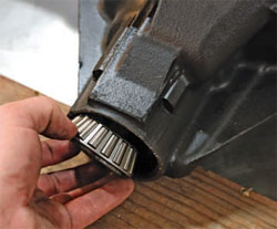
Although this inner bearing did not seize, the bluing on the bearing rollers means it was close to failing. If it had failed, it could have cracked the rear-end housing.
Step 3: Inspect Pinion Shim

Under the bearing is the factory shim. You can try to reuse it, but you will likely have to add shims or replace it with a thinner shim to get the new gears to mesh correctly.
Step 4: Inspect Pinion Shim (CONTINUED)

Several new shims are included with a rebuild kit. A shim sets the pinion depth; it is not a wear part. Shims come in varying thicknesses, but it is always a good idea to start with the original one and go from there.
Step 5: Install Inner Bearing

The inner bearing is a press-on part, so you need a slip-fit bearing as a stand-in for setting up the gears. Modify the original bearing (it will be replaced) for fitment over the pinion gear. Use a carbide burr or sanding roll with a die grinder to open it up just enough so that it slips on and off the new pinion gear easily.
Step 6: Install Inner Bearing (CONTINUED)

Once the bearing has been modified, slip the shims over the pinion shaft and place the bearing on top of them.
Step 7: Install Pinion Gear in Housing (Professional Mechanic Tip)
You need to perform an initial fitment so you need to mock up the differential in the housing before you perform the final assembly. Place the pinion in the case and prelube the bearings so that they don’t stick.
Step 8: Install Solid Spacer

All GM 10- and 12-bolt axles use crush sleeves. Do not install the crush sleeves yet; you are simply trying to figure out the initial settings. The crush sleeves should only be used for final assembly because once they crush, they can’t be reused.
Step 9: Install Solid Spacer (CONTINUED)

A solid spacer is an alternative to a crush sleeve. It does not crush; rather, it uses shims to set the pinion pre-load. It is re-useable and not difficult to set up.
Step 10: Install Solid Spacer (CONTINUED)

Push the crush sleeve in from the front of the case. If you are setting up a solid spacer sleeve, wait until the pinion depth is set to do so.
Step 11: Install New Pinion Bearing
Install the new front bearing into the case. On new pinions, the bearing is likely very tight. You may need to use the yoke and pinion nut to pull the pinion into the bearing.
Written by David Vizard and posted with permission of CarTech Books
This tech tip is from the full book, CHEVY DIFFERENTIALS: HOW TO REBUILD THE 10- AND 12-BOLT.
For a comprehensive guide on this entire subject you can visit this link: LEARN MORE ABOUT THIS BOOK HERE
SHARE THIS ARTICLE: Please feel free to share this post on Facebook Groups or Forums/Blogs you read. You can use the social sharing buttons to the left, or copy and paste the website link: https://www.cartechbooks.com/blogs/techtips/how-to-rebuild-gears-in-chevy-and-gm-differentials-step-by-step