
The components involved in the engine’s air and fuel intake, combustion, and exhaust process are revealed in this chapter. In order to better understand the function of the exhaust system, it helps to first understand how the air and fuel charge enters the engine and how it is influenced by the chain of events that include intake air, carburetor or throttle body, intake manifold, fuel metering, cylinder heads, cam-shaft, exhaust manifold or tubular headers, and the engine’s intake, compression, power, and exhaust strokes.
THIS TECH TIP IS FROM THE FULL BOOK: PERFORMANCE EXHAUST SYSTEMS
For a comprehensive guide on this entire subject you can visit this link: LEARN MORE ABOUT THIS BOOK HERE
SHARE THIS ARTICLE: Please feel free to share this article on Facebook, in forums, or with any clubs you participate in. You can copy and paste this link to share: https://www.cartechbooks.com/blogs/techtips/performance-exhaust-basic-principles-and-design
In almost all cases, mufflers are required in order to meet sound-level laws, especially for any street-driven vehicle. In addition, catalytic converters are required for vehicles that were originally so equipped. Here, I discuss the role that mufflers and converters play, and offer tips on enhancing both components from a performance perspective. I discuss various muffler styles, as well as catalytic converters that are available specifically designed for high-performance applications.
A rule of thumb is to determine engine intake volume and then approximately match this volume for the exhaust. This begins by selecting the appropriate intake manifold and carburetor size, as well as other variables such as cylinder head intake port volume, camshaft profile, and compression ratio. Factors such as these can affect your choice of header primary tube diameter and exhaust pipe diameter. In simple terms, as you generate more cylinder pressure and horsepower, additional exhaust volume likely needs to increase in order to accommodate the engine’s capability to breathe.
Intake Air
Cool intake air is denser than warm air. Higher air density means more oxygen molecules, which provides more intake air charge and more power. Obviously, the more air you can draw into an engine the more horsepower it generates. A cold-air intake refers to an air inlet system that feeds from air that is cooler than the air inside the engine compartment. The farther away from the engine’s heat, or the more isolated the air is from engine heat, the cooler the air that’s available to feed the engine.

A cold-air filter connects to the engine intake with ducting, relocating the filter element farther away from the engine heat source, placing the filter close to a colder fresh-air source. Cold-air systems are offered for specific vehicle applications, with a cold-air shroud that helps to capture more air directly to the filter. (Photo Courtesy K&N Engineering)

The air intake system on this drag-race car’s LS7 engine, built by Hutter Engineering in Chardon, Ohio, is both efficient and gorgeous. The ducting that feeds air to the throttle bodies is fabricated using carbon-fiber tubing. Cold air is routed from the nose of the car directly to the engine, with no engine-bay hot air entering the intake airstream.

A cone- or barrel-style air filter may also allow establishing a cold-air intake for universal applications, such as in race car engine bays. While still within the confines of the engine bay, this filter has been located farther away from the engine.

Air filter elements ideally should be as large (in terms of surface area) as possible, limited primarily by the confines of the engine bay. In-expensive air filters sometimes provide excessive restriction. Even if they offer acceptable flow, cheap paper elements may not provide much in the way of usable life. It’s best to buy superior filters when the budget allows. Some filters are designed to be reusable; they require washing and drying before placing them back into service. (Photo Courtesy K&N Engineering)
One often-ignored aspect is using a cold-air intake. It is an open-element air filter that’s located close to the ground, but it runs the risk of creating a hydrolock in the engine. This can occur if the air filter is exposed to excessive water (for instance, when driving though high-standing water where water may be drawn directly into the intake system). If water enters the engine and makes its way to the combustion chambers, it is possible for the water to build to the point where it prevents the pistons from reaching top dead center (TDC), creating a hydraulic lock. Remember that while you can compress air, you can’t compress a liquid. If hydro-lock occurs, it can take the engine out in a big way, including bent connecting rods, destroyed rod bearings, busted pistons, and more. Unless the vehicle is to be street driven only in dry weather, or used only on a drag strip, locating the air filter(s) low and close to the ground isn’t an issue. If you plan to operate in wet conditions, be aware of this.
The intake system, including air intake and carburetor (or fuel injection system), has a direct impact on airflow through the engine and subsequently the flow capabilities of the exhaust system. Always keep in mind that what enters the engine also needs to leave the engine. Engine analysis software tools, such as Ricardo and others, provide assistance in developing a system to determine cross sections and volumes from the air filter inlet to the exhaust collector outlet.
Carburetors
A carburetor’s job is to deliver the air/fuel mixture that the engine requires for any given state of engine operation. The carburetor mixes fuel and air in the correct ratio, or proportion. In order to create combustion, the fuel charge needs to be mixed with air to atomize the mixture.
A carburetor’s inlet system features a fuel bowl, where a specific amount of liquid fuel is stored. A float inside the bowl features a tapered needle that engages into a seat orifice. The adjustment level of the float, along with fuel pressure, maintains the correct fuel level in the bowl. As the fuel level drops, the float drops; this moves the needle away from its seat, allowing fuel to enter the bowl. When the fuel level rises to its adjusted setting, the float rises, moving the needle toward its seat. This simple float-activated needle and seat system maintains the required level of fuel within the bowl, providing the adequate amount of fuel to be delivered to the carburetor’s metering system.
Fuel inlet pressure, the pressure created by the fuel pump, directly affects float level. If too much fuel pressure is present, the float rises, causing the engine to run too rich, with excess fuel spilling/venting into the carburetor’s air inlet. If fuel pressure is too low, the float drops and lowers the bowl fuel level, resulting in decreased fuel delivery to the main jets, promoting a lean condition.
A fuel-injected system requires a high fuel pressure, often in the 30- to 40-psi range, in order to provide instant fuel delivery when the injectors open. On the other hand, a carbureted fuel system requires a relatively low fuel pressure, commonly in the 4- to 6-psi range. In a carbureted system, too-high fuel pressure overwhelms the float, causing the float to rise too far. Whenever an electric fuel pump is used, you need to pay attention to its rated pressure output. If the pump is rated to produce in excess of about 6 psi, a fuel pressure regulator must be installed in the fuel line. The best setup is to use an adjustable pressure regulator along with a pressure gauge, to allow you to adjust and verify fuel pressure.
From the bowl area, fuel flows through main jets, which control the flow of fuel into the carburetor’s metering system. Main jet sizes are based on venturi size, atmospheric pressures, and ambient operating temperatures. The venturi provides a point of constriction for incoming air, acted upon as the down-stroke of the pistons creates a vacuum signal. As air runs through the venturi, it increases speed and then creates a pressure drop as it exits the venturi. This pressure drop promotes fuel from the bowl into this vacuum pull, pulling fuel through the discharge nozzle in the boost venturi. The mixture of fuel with air atomizes the fuel.

A 4-barrel, or secondary-type, carburetor offers more fuel than a 2-barrel when the secondaries are opened. The primary side is used for light throttle demands and the secondaries deliver maximum air/fuel delivery for heavy acceleration.
A passage in the carburetor applies vacuum to a power valve located between the bowl and metering system. At engine idle speed, vacuum is highest. At idle, high vacuum keeps the diaphragm in the power valve closed. As the throttle opens during increased demand, vacuum drops, which allows the spring inside the power valve to overcome vacuum and opens the diaphragm. This allows added fuel to flow through the valve, richening the fuel mixture to accommodate the increase in throttle-opening air demand. In other words, when you open the throttle, the power valve provides added fuel.
An accelerator pump, located at the bottom of the bowl, serves as a mechanically operated fuel injector that supplies an extra shot of fuel when the throttle is opened suddenly/quickly. This added shot of fuel reduces or eliminates the chance of a stumble or lag upon sudden throttle opening. The accelerator pump features a lever that is actuated by the throttle linkage.
A 4-barrel, or secondary-type, carburetor broadens the power output potential by adding more air and fuel delivery when engine demands require more delivery. A secondary-type carburetor is essentially two carburetors in a single package. Both the primary and secondary sides feature their own metering systems. The primary side is used for light throttle demands; the secondary side is designed to operate when additional or maximum air/fuel delivery is required. The secondary side activates either mechanically, via the carburetor throttle linkage, or by vacuum, utilizing a diaphragm that opens the metering circuit based on engine vacuum. A vacuum-operated secondary-type carburetor is more forgiving because the secondaries open only as required according to the engine’s vacuum signal. There-fore, this type of carburetor offers more latitude, allowing the use of a slightly larger CFM rating in contrast to a mechanically operated secondary that is controlled by the driver’s throttle control.
Choosing Carburetor Size
Many are tempted to run a big- carburetor, in terms of CFM rating, assuming that this automatically results in added power. Some even choose a larger carburetor simply for bragging rights. Like so many other engine components, bigger isn’t necessarily better. The volume of the carburetor must be matched to the engine’s needs. You need to match the carburetor according to the engine’s volumetric requirements.
Volumetric efficiency (VE) refers to the engine’s ability to breathe. VE represents a ratio of the weight of the incoming ambient air to the theoretical volume of air that the engine can consume at the anticipated engine RPM at which it makes maximum torque. VE is expressed as a ratio of these two factors. A stock, low-performance engine likely features about 80-percent VE at its maximum torque range, while a modified, better breathing performance engine may feature a VE in the 85- to 90-percent range. If you refer to carburetor CFM size for a given engine displacement and peak-torque RPM, you can determine what size carburetor is appropriate, based on a theoretical 100-percent VE. You then multiply peak RPM by the engine’s VE in order to determine what the actual carburetor size should be.

This chart aids in selecting a carburetor size for anticipated wide-open throttle (WOT) at the engine’s lowest RPM. (Photo Courtesy Holley Performance Products)

This chart aids in carburetor selection based on engine-operating RPM. For example, a 400-ci engine theoretically requires about 800 cfm when operating at about 6,800 rpm. Factors such as cylinder head, intake manifold, and cam specifications are variables that come into play. The chart provides a good starting point for carburetor selection. (Photo Courtesy Holley Performance Products)
The higher the engine’s VE, the bigger the carburetor it can utilize. VE can be increased by increasing the engine’s breathing, which can entail using a camshaft with more duration, choosing a more efficient and freer-flowing intake manifold, improving the exhaust system flow, cylinder head porting, and reducing the engine’s parasitic losses by accurizing all clearances, achieving proper cylinder bore surfaces finish, enhanced rotating assembly balancing, and taking advantage of specialized anti-friction and oil drain-back coatings, etc.
In the most basic terms, the larger the engine displacement and the higher the engine speed, the more air it can consume; therefore, the larger the carb can be.
THIS TECH TIP IS FROM THE FULL BOOK: PERFORMANCE EXHAUST SYSTEMS
For a comprehensive guide on this entire subject you can visit this link: LEARN MORE ABOUT THIS BOOK HERE
SHARE THIS ARTICLE: Please feel free to share this article on Facebook, in forums, or with any clubs you participate in. You can copy and paste this link to share: https://www.cartechbooks.com/blogs/techtips/performance-exhaust-basic-principles-and-design
Simple Carb Formula
The following formula may be used to roughly determine carburetor size based on engine displacement and maximum engine speed:
Maximum Carb CFM = (CI ÷ 2) x (maximum RPM ÷ 1,728)
Where:
CFM = cubic feet per minute
CI = cubic inches of displacement RPM = revolutions per minute
(engine speed) 1,728 = math constant
As an example, a 403-ci engine produces peak power at a maximum of 6,500 rpm. Using the formula:
[(403 ÷ 2) x (6,500 ÷ 1,728)]
201.5 x 3.76 = 757.64
Here, a carburetor size of 700 to 750 cfm is appropriate.
A vacuum-secondary carburetor is somewhat forgiving, allowing you to use a slightly larger carburetor. A carburetor with mechanical secondaries is not so forgiving. If in doubt when deciding between two sizes in the required range, it’s often better to choose the smaller carburetor. Selecting a mechanical secondary carburetor that features a double-pumper design that is too large for the application can result in sags or bogs upon acceleration if the engine uses up the pump shot before the main fuel shot is delivered.

Forced-induction engines utilizing either supercharging or turbo-charging can take advantage of larger carburetors, since forced-induction can typically increase VE to a point well over 100 percent.
EFI Throttle Bodies
EFI is an active system that adjusts fuel delivery according to the operating conditions of the engine while a carburetor is a passive system that controls both air and fuel intake. The engine control unit (ECU) manages an electronic fuel-injection system’s fuel delivery, and it precisely controls fuel delivery timing and duration via the injectors. I could refer to a throttle body as the engine’s air valve. The throttle body’s only job is to allow air to enter the engine. In theory, the more air delivered, the more power the engine can produce; of course, when mixed with the appropriate ratio of fuel. Changing an original equipment manufacturer’s (OEM) throttle body for a larger aftermarket throttle body is necessary in order to introduce more air, but there is a point of diminishing returns. Going with the largest throttle body available isn’t necessarily the best move.
Throttle body size, in terms of throat diameter, needs to be properly sized to the displacement of the engine. If the throttle body is too small, air velocity is faster, but volume is often insufficient. If the throttle body is too large, the air velocity is typically too slow, but more air is drawn into the engine.
An accepted formula for determining throttle body size in millimeters is based on engine displacement, measured in cubic inches of displacement (ci):
Throttle Body Size (mm) = √[(ci x 196.3 x RPM at max. hp) ÷ 67,547]
Where:
196.3 = math constant
67,547 = math constant
For instance, let’s say that the engine features 408 ci, and this engine is expected to reach maximum horsepower at 6,500 rpm. Using the formula:
(408 x 196.3 x 6,500) ÷ 67,547
7,707.0425 = 87.7897 mm
For this naturally aspirated engine example, a throttle body featuring an 88- to 90-mm throttle body is approximately the correct size. Slightly increasing the size provides a small cushion for maximum horsepower. In this example, a throttle body size of around 90 mm does not restrict the air needed for this engine at a speed of 6,500 rpm. While you could go with an even larger throttle body, air speed (velocity) may slow down and not fill the chambers quickly enough.
If you grossly oversize the throttle body, you introduce a lot of air very quickly, which may be too much air for the engine to handle during quick or snap-throttle activation, possibly making the vehicle undrivable on the street, while at the same time not improving horsepower.
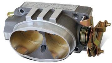
Throttle bodies for electronic fuel injection systems manage incoming air only. Moving to a larger-volume throttle body can often improve performance, as long as the engine can use the increased air volume. (Photo Courtesy BBK Performance)
If you’re running a forced- induction system, throttle body size becomes slightly less critical, since the supercharger or turbo-charger forces air into the engine. A Roots-style supercharger sucks air into the engine through the throttle body, while a turbocharger pushes air through the throttle body. The goal here is not to create a too-small bottleneck restriction for airflow.
Air pressure, as well as air density, is approximately twice as high in a turbo setup as compared to a naturally aspirated engine, so in theory you can use a smaller throttle body for a turbo as compared to a naturally aspirated setup.
Mass Airflow Sensors
A variety of methods of monitoring airflow have been used in production vehicles over the years, including now-outdated van air-flow meters, Karman Vortex airflow meters, and speed density systems that rely on a host of engine sensors to determine airflow. The most common systems today use either a hotwire or a hot-film mass airflow (MAF) sensor. A hot-wire or hot-film MAF sensor allows the electronic control module (ECU) to directly measure intake air temperature, humidity, and air density. A hot-wire MAF sensor features a thin platinum wire located in the airstream that is heated to a programmed temperature using a reference voltage of around 5V supplied from the ECU. As intake air passes the wire, the wire is cooled, resulting in a change in resistance. As the wire temperature drops, the voltage changes. The ECU sees this drop and manages the voltage signal for operating conditions. Based on the required voltage changes, the ECU is able to determine the quality of the air mass.
A hot-film MAF sensor operates in a similar manner, featuring a heated film. One side of the film maintains a constant reference temperature, while the other side is exposed to intake air. The difference in temperature allows the ECU to determine incoming air quality. The ECU uses this information, in combination with other sensors, to determine fuel injection delivery.

This MAF sensor is mounted to a section of air intake ducting. A hot-wire or hot-film MAF sensor allows the ECU to directly measure intake air temperature, humidity, and air density. A hot-wire MAF features a thin platinum wire located in the airstream that is heated to a programmed temperature using a reference voltage of around 5V supplied from the ECU. As intake air passes the wire, the wire is cooled, resulting in a change in resistance. As the wire temperature drops, the voltage changes. The ECU sees this drop and manages the voltage signal for operating conditions. Based on the required voltage changes, the ECU is able to determine the quality of the air mass.

A MAF sensor is located between the air intake/filter and the throttle body, and it measures the flow rate of air that enters an engine. Note the platinum wire in this MAF sensor. Foreign matter easily contaminates these fragile wires. Never assume that a MAF sensor is faulty. Inspect the contact terminals to make sure that the connector is fully seated. That is first thing you can do to make sure it is operating properly.
Dirt, oil, spider webs, etc. can contaminate a MAF sensor wire (or film). If the MAF sensor is contaminated by oil, the cause is usually oil vapor from the PCV system in terms of blowby oil that makes its way past the piston rings.
It’s recommended that you clean the MAF sensor every time you ser-vice your air filter. The MAF sensor is located in the engine air duct, between the air box and the throttle body. The sensor is generally secured with two screws. Disconnect the wiring harness connector from the sensor and remove the sensor. Do not touch the platinum wire or film with your fingers. This can leave residue on the sensor wire surface. Clean the sensor air passage and wire using only a MAF sensor cleaner spray. Don’t use a brake cleaner or other type of sol-vent, as this can damage or further contaminate the sensor. Once the sensor is dry, re-install it. A fouled MAF sensor can cause a rough idle, hesitation, or poor performance at wide-open throttle (WOT).
THIS TECH TIP IS FROM THE FULL BOOK: PERFORMANCE EXHAUST SYSTEMS
For a comprehensive guide on this entire subject you can visit this link: LEARN MORE ABOUT THIS BOOK HERE
SHARE THIS ARTICLE: Please feel free to share this article on Facebook, in forums, or with any clubs you participate in. You can copy and paste this link to share: https://www.cartechbooks.com/blogs/techtips/performance-exhaust-basic-principles-and-design
Fuel Injector Sizing
The formula below that can be used to estimate fuel injector rating, based on injector pounds-per-hour. While not having a direct effect on your exhaust system design, properly matching injector sizes to the engine is one step in optimizing power and efficiency. In an injected system, information obtained from the oxygen and air/fuel sensors in the exhaust stream is used by the ECU to help establish the required air/fuel mixture. If the injectors are not sized properly for the engine, efficiency and power isn’t maximized, regard-less of the exhaust system design. One of the factors you consider is brake specific fuel consumption (BSFC).
This is the ratio between the engine’s fuel use and engine power output. At engine idle, the ratio is high due to the throttle being closed. At peak torque, BSFC is low during this point of maximum fuel efficiency. BSFC increases as the engine revs beyond peak torque toward maximum horsepower. BSFC is reduced as engine efficiency increases due to less friction and less drag, such as when the engine features lower tension piston rings, an improved oil scavenging system and/or when drainback coatings are applied to the crankshaft and connecting rods, the use of an electric water pump to reduce crankshaft drag, etc.

Another factor for calculating injector size is injector duty cycle. Most typically, this is about 80 percent.
Injector Rating = (engine HP x BSFC) ÷ (number of injectors x injector duty cycle)
For example, using the formula for an 8-cylinder engine that produces 500 hp and features a turbocharger:
500 x .5 = 250
8 injectors x .8 = 6.4
250 ÷ 6.4 = 39.06 lbs/hr
In this example, fuel injectors with a rating of about 39 lbs/hr should be adequate and provide a good starting point. If the BSFC is .6, the suggested injector size is around 46 lbs/hr (500 x .6 ÷ 6.4 = 46.875).
Intake Manifolds
The intake manifold directs air-flow from the carburetor/throttle body to the cylinder head intake ports. The choice of intake manifold style and size of the runners affects the horsepower and torque range, influenced by factors such as cross sectional area and runner length. Generally speaking, a single-plane intake manifold is best for higher RPM power, while a dual-plane design is best suited for lower-RPM and torque at lower RPM.
In terms of the plenum location, again in general terms, taller runners, and higher plenum locations are best suited to accommodate higher engine RPM and power at higher RPM bands.
You always need to be aware; air/fuel that comes in must be able to get out of the engine so you must select your exhaust system according to these factors. Shorter exhaust primaries dump the engine exhaust pulses more quickly to better accommodate higher RPM, while longer primary tubes can improve exhaust scavenging to benefit a lower-RPM power-band. Header primary tube diameter and length affect how the exhaust gases are pulled out of the cylinder head exhaust ports, as scavenging of exhaust can create a vacuum effect, not only pulling exhaust out but aiding in pulling in additional intake charge.
The configuration of the intake manifold runners directly affects power and where maximum torque occurs. Without discussing a specific engine application in terms of displacement, cylinder head design, and camshaft profile, I address intake manifolds in general terms. In addition to intake manifold runner length, you need to consider runner volume, including length and cross section area. A larger cross-section area and shorter runner length is better suited to higher-RPM ranges and larger-displacement engines, while a smaller cross-section area and longer runner length is better suited to smaller-displacement engines and lower-RPM ranges. Most engine intake manifolds are a compromise by design, a balance between engine power output and low-RPM torque to suite the intended application and driving conditions.
If the cross-section area is too large for the application, a reduction in peak torque can occur and the RPM range of where peak torque is created can increase. On an engine dyno graph, peak torque generally indicates where in the RPM range VE is the greatest.

A single-plane intake manifold features a single open plenum that feeds all eight cylinders. Runners are typically shorter than a dual-plane manifold for a more-direct shot at each cylinder, which is generally better for higher-RPM power. Single-plane manifolds also usually feature a bit of an air gap between the runners and block, which aids in reducing the air/fuel temperature. A single-plane manifold is likely a better choice as the engine usually runs above about 2,500 rpm. If you plan to operate the engine primarily at 2,500 rpm or less, a dual-plane manifold may be the better choice.

A dual-plane intake manifold features a split plenum, providing an intake charge every 180 degrees of crank-shaft rotation. (They are often referred to as 180-degree manifolds.) Intake runners are usually longer than on a single-plane manifold. A dual-plane is generally better suited to low-end torque and power for street use. Regard-less of the application, pay attention to the advertised engine RPM operating range for both the manifold and the camshaft that you plan to use. Try to match the manifold to the cam based on those ratings.
Because of its split design, a dual-plane manifold is generally better suited to lower-RPM operation, enhancing overall driveability. That doesn’t mean that a dual-plane manifold isn’t suited for high-performance use, however. It depends on the powerband. In general terms, lower-RPM use is likely a better choice for a dual-plane and higher-RPM use is better accommodated with a single-plane manifold.

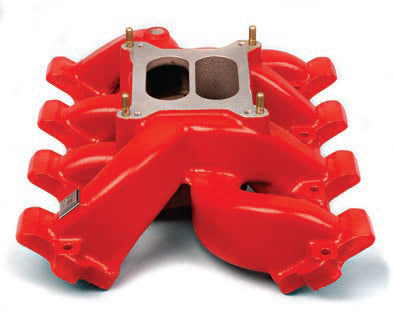
High-rise tunnel ram manifolds are best suited for extended high-RPM use and provide more torque and horsepower over a longer range (during higher engine speed). Modular high-rise intake manifolds (often called tunnel rams because of the long single-plane intake runners) are available that accommodate either a single 4-barrel carburetor or dual carbs. This example of a Holley Hi-Ram intake manifold is fitted with an upper plenum that allows mounting a pair of carburetors sideways, or in-line, depending on the carburetor dimensions and desired throttle link-age setup.

Certain electronic fuel injection intake manifold designs feature a central forward-mount throttle body and a series of equal-length intake runners directly to each cylinder. (Photo Courtesy BBK Performance)

This cutaway view of a carbureted intake manifold provides a good view of the plenum dividers. (Photo Courtesy Holley Performance Products)

High-rise intake systems, by virtue of their design, raise the carburetor(s) well above the engine. Hood clearance issues are commonly solved by the installation of a tall hood scoop.

In addition to cast-aluminum EFI intake manifolds, lighter-weight manifolds are also available made from advanced polymer material for better heat dissipation. Because of their design and construction, these are two-piece manifolds with lower and upper sections. A cooler intake charge provides a denser air charge, which in turn promotes increased power. Another benefit of the polymer manifold is its ability for designers to create smoother and more-laminar airflow more easily. (Photo Courtesy FAST/Comp Cams)

Carbureted intake manifolds commonly feature divider walls in the plenum to aid in directing the air/fuel charge to the cylinders. These walls are also designed to help in breaking up, or atomizing, the charge to pre-vent creation of large fuel droplets.
Note that these generalizations apply to naturally aspirated engines. When you consider an engine fed by forced induction, whether that involves a turbocharger or super-charger, intake manifold runner design becomes less critical because the air charge is forced into the cylinders under a positive pressure. Matching the intake manifold runners to the selected cylinder heads is the goal, in terms of port cross-section area, in order to maximize efficiency in terms of airflow.
Port matching (where the intake manifold exit ports match the size and shape of the cylinder head intake ports) is an important step to maximize airflow. The intent is to precisely mate the location, shape, and size of the intake manifold’s air exit to the cylinder head intake port entry. If the ports are mismatched (for instance if the port walls are not aligned or if the intake manifold ports are larger than the cylinder head intake ports), incoming air hits the exposed walls, creating unwanted turbulence. Mounting a poorly matched intake manifold to the best set of cylinder heads can easily reduce power and prevent taking advantage of the engine’s maximum potential. Intake manifold runners are commonly designed with a slight taper to promote airflow velocity, enhancing airflow speed on its way to the cylinder head.
Many single-carbureted intake manifolds feature unequal-length intake runners, and thus the front and rear runners are longer and narrower than the center runners, which may be shorter and wider in comparison. In theory, this equalizes or balances the volume of air distributed to the cylinders. In addition, airflow velocity must be considered. As a result, the shape of the intake manifold runners (runner tapering and the degree of turns in the runner) may be tuned in order to equalize airflow velocity to all cylinders.
Custom sheet-metal intake manifolds are constructed of billet aluminum tubes and panels and welded together while stock manifolds are made of heavier-wall cast aluminum. Material and weld strength becomes a critical concern when dealing with a forced-induction setup, due to the repeated cycles of pressurized air within the manifold. This requires high-strength aluminum, such as 6061 billet.
In addition, when using a welded intake manifold, the plenum box volume becomes critical for a naturally aspirated application. Therefore, the plenum volume should ideally match the engine displacement to eliminate the possibility fuel starvation for individual cylinders. For instance, if the engine displacement is 408 ci, the plenum volume should provide 408 ci. If plenum volume is too small, upper-RPM power can suffer. This becomes more of a critical issue for competition engines in contrast to street-driven engines.
Cylinder Heads
Cylinder heads are a key component to the overall airflow system of an engine and should be one of the first hard parts to consider when creating a plan for a new engine build. They are responsible for conditioning the air/fuel intake charge into the cylinder, aid in the conversion of chemical and thermal energy into mechanical energy, and process spent exhaust gases into the engine exhaust system. Once the cylinder heads have been determined for an engine build, the selection of support components, such as intake manifolds, pistons, exhaust headers, and camshafts, becomes less cumbersome to choose the right combination of parts to achieve the desired outcome. Each component of the engine airflow system must work together to achieve an efficient flow path, while minimizing flow restrictions, based on a given engine volume displacement. Most performance V-8 cylinder heads are of overhead-valve (OHV) design, where the intake and exhaust valves are positioned above the engine cylinder bore for maximum intake and exhaust efficiency.
As you increase the intake-side flow, you must also increase the exhaust-side flow to avoid exhaust restriction. As you pack increased airflow and feed more fuel into the engine, the exhaust system must be able to evacuate exhaust gases accordingly. The need for a less-restrictive exhaust system and the ability for the exhaust system to pull, or scavenge, the exhaust becomes increasingly important. This is where moving to an appropriate tubular-header system provides a distinct advantage in contrast with a set of OEM cast exhaust manifolds.

Selecting the Right Cylinder Heads
In the performance aftermarket, there is an overabundance of cylinder head choices for most popular engine applications. Consumers can purchase complete brand-new performance aftermarket cylinder heads or rework OEM cylinder head castings through hand porting or by high-tech CNC (computer numeric control) porting. Whatever the engine goal, cylinder heads must be sized properly to the volume displacement of an engine, operate in the intended RPM range of the vehicle application, physically fit into the desired chassis space, and function effectively with support components such as intake manifolds, exhaust headers, and camshafts.
Most aftermarket cylinder head manufacturers rate performance cylinder heads based on engine volume displacement, RPM, and application (on-road only, race only, or both).
Generally, a smaller intake port volume range creates torque at a lower RPM compared to a larger intake port volume for the same engine application. Always consult the cylinder head manufacturers’ product data for specific engine builds and support components for comparison between intake port volumes.
Intake Port
Cylinder head intake port shape, cross-section area, and volume can be considered limiting factors when discussing engine performance in naturally aspirated applications. Generally speaking, most engines that perform well in naturally aspirated form perform even better when forced-induction strategies or nitrous oxide is added.
Intake port shape is dictated by the envelope of space given by the overall design of an engine, valve-train layout, and intended vehicle application. In terms of pushrod-type engines, the intake port width must not be much larger than the distance between the pushrods, generally called the “pinch point” of an intake port. There are several strategies for increasing the distance between pushrods, including offset lifters, offset rocker arms, and compound valve angles.
The length of a cylinder head intake port is established by its location relative to the centerline of the cylinder bore and intake manifold mating flange. Height of an intake port is determined by space constraints of matting components such as intake manifolds, valve covers, and valvetrain hardware. Generally speaking, intake ports with larger corner radii outperform port designs with smaller corner radii, based on the cross-section shape transition from the intake port opening to the valveseat sealing surface.
Intake port cross-section area is one of the most important dimensions when determining the cylinder head airflow requirements for a particular engine size. Equations derived from fluid dynamics science tells you that a given cross-section area is only going to flow so much fluid based on its speed, mass, temperature, and compressibility. Most computer engine analyzer software programs require an intake port minimum cross-section area input to calculate potential torque and horsepower estimates of an engine.

Valve angle is referenced relative to 90 degrees from the block deck surface. A smaller intake port volume generally creates torque at a lower engine RPM compared to a larger intake port volume on the same engine.

Exhaust ports have smaller volume and cross-section area than intake ports because exhaust gases are pushed out by the pistons and pulled out by exhaust system scavenging.
Intake port volume is basically a function of the length, width, and height of the intake port shape that fits into established space constraints. Marketing trends in the performance aftermarket can be misleading because cylinder heads are categorized in most cases by their intake port volume rather than minimum cross-section area. Technically, a cylinder head with an intake port volume of 180 cc could outperform a cylinder head with a 195-cc intake port if the cross-section area of the 180-cc port is larger.
As mentioned earlier, whenever you increase the engine’s intake flow, the exhaust flow must be increased to avoid exhaust stream restriction. High-performance aftermarket cylinder head designs often feature raised exhaust ports. Raising the exhaust port location on the cylinder head generally results in an increase of exhaust flow, since this provides a more-direct path. Aftermarket performance cylinder head manufacturers invest quite a bit of time and testing in an effort to develop improvements in power. Raised-port cylinder heads are offered for applications where this has provided a benefit based on their extensive testing.
Exhaust Port
Cylinder head exhaust ports function in reverse compared to intake ports in that the exhaust gas flow enters the exhaust port from the face side of the valve, rather than the stem side of the valve in an intake port. Generally, exhaust ports are smaller in volume and cross-section area compared to intake ports, flowing 15 to 40 percent less on average. This is because exhaust gases are pushed out of the cylinder by the piston, and also pulled out at the same time by the exhaust header system, referred to as exhaust scavenging.
Exhaust port shape is dictated by space constraints of exhaust headers, spark plugs, and vehicle/chassis clearance. Generally a longer exhaust port shape outperforms a shorter exhaust port, with both having the same cross-section area. This is because turning the exhaust gases out of the cylinder head and into the exhaust system is more efficient. In most cases, the diameter of the exhaust header primary tube needs to be at least the same or larger than the diameter of the exhaust valve; otherwise a flow restriction could be created. The bulk volume of flow in an exhaust port generally follows the longer side of an exhaust port, which is why there are trends to “D-shaped” exhaust ports, with the straight side toward the bottom of the port.

Combustion Chambers and Valve Angles
Combustion chambers in cylinder heads come in a variety of different shapes and sizes depending on the engine application. The combustion chamber’s main functions in a cylinder head is to aide in the intake cylinder filling, compressing the air/fuel mixture, controlling flame travel during ignition, and processing exhaust gases into the exhaust port.
Combustion chamber volume and shape design has a major effect on the static compression ratio in an engine, the amount of ignition timing advance that can be added, and the output emissions through the exhaust system. Some modern engines use two spark plugs per cylinder to achieve maximum efficiency, while reducing exhaust emissions by more complete combustion.
Valve angles and combustion chamber volume are directly related to one another. Generally, valve angle is measured 90 degrees (perpendicular) from the cylinder head deck. In the case of OEM GM LS cathedral-port cylinder heads, the valve angle is 15 degrees. For the sake of comparison, early small-block Chevrolet cylinder heads feature 23-degree valve angles.

The combustion chamber aids in the intake cylinder filling, compressing the air/fuel mixture, controlling flame travel during ignition, and processing exhaust gases into the exhaust port.

Citing the GM LS cathedral-port cylinder heads as an example, valve angle is established at 15 degrees, compared to 23-degree valve angles featured in early small-block Chevrolet cylinder heads. Numerically lower valve angles allow for a shallower combustion chamber, resulting in lower combustion chamber volume.
Numerically lower valve angles allow for a shallower combustion chamber, resulting in lower combustion chamber volume. Numerically higher valve angles require a deeper chamber, resulting in a larger combustion chamber volume.
It is important to note that valve angles affect the amount of clearance between the valves and pistons. Choosing the right combination of camshaft, piston, and cylinder head is crucial to the reliability of the engine build. A general rule of thumb for valve-to-piston clearance is .080-inch intake and .120-inch exhaust, measured +/- 15 crankshaft degrees from intake top dead center.
Camshafts
Throughout this book, I talk about exhaust gas scavenging. This refers to the engine’s system being able to pull the exhaust gases out of the engine. The more exhaust volume pulled out, and the faster it’s pulled out, the more the air/fuel mixture is allowed to be drawn in. Efficiently burning more air and fuel means more power.
Positive exhaust pressure runs from the exhaust ports to the end of the exhaust pipe. The pressure wave collapses at the exit, and a negative pressure wave is created that tries to return to the cylinder head’s exhaust port. Ideally, you want the negative pressure wave of the exhaust gas to hit the exhaust valve just before the valve closes.
Due to valve overlap, the intake valve starts to open while the exhaust valve is still open (with the exhaust valve off its seat before it closes). This helps reduce cylinder pressure, allowing a more efficient intake stroke. As the piston moves up during the exhaust stroke, exhaust gas is pushed out. When the intake valve starts to open just before the piston hits TDC, and with the exhaust valve still open, the exhaust gas helps to pull the air and fuel charge into the cylinder.
Particularly in a naturally aspirated engine, where forced induction isn’t a factor, this valve overlap aids in both exhaust push and intake charge entry. The higher the planned engine RPM, the more intake and exhaust valve overlap is needed.

When choosing your camshaft, pay attention to lobe separation angle (LSA). A tighter (smaller number) LSA tends to move torque to a lower RPM range, while increasing maximum torque. A wider (larger number) LSA tends to move the torque to a higher RPM range.
Camshaft Timing
When the camshaft is advanced the intake valve opens sooner and the engine delivers more low-end torque. Advancing the camshaft also decreases intake valve-to-piston clearance and increases exhaust valve-to-piston clearance.
Retarding the camshaft keeps the intake valve open later and thus delays the intake closing. This helps generate power at higher engine RPM. Retarding the camshaft also increases intake valve-to-piston clearance, while decreasing exhaust valve-to-piston clearance.
THIS TECH TIP IS FROM THE FULL BOOK: PERFORMANCE EXHAUST SYSTEMS
For a comprehensive guide on this entire subject you can visit this link: LEARN MORE ABOUT THIS BOOK HERE
SHARE THIS ARTICLE: Please feel free to share this article on Facebook, in forums, or with any clubs you participate in. You can copy and paste this link to share: https://www.cartechbooks.com/blogs/techtips/performance-exhaust-basic-principles-and-design
Lobe Separation Angle
The lobe separation angle (LSA) refers to the number of degrees between the centerlines of the cam-shaft’s intake lobe and the exhaust lobe. Differences in LSA have an effect on engine performance. For example, a camshaft may feature a 108-, 110-, 114-, or 118-degree LSA.
The tighter the LSA is, the smaller the LSA number. Tightening the LSA tends to move engine torque to a lower RPM and increases maximum torque with a narrower power-band. A tighter LSA also builds higher cylinder pressure and increases the engine’s effective compression. The increase in compression also increases the possibility of detonation/knock, which may require the use of higher-octane fuel. Engine vacuum at idle is decreased, with a degradation of idle quality, and valve-to-piston clearance tightens up. A tighter LSA moves torque at a lower engine RPM, increases maximum torque, and provides a narrower powerband. In addition, it increases cranking pressure, reduces idle vacuum, increases valve overlap, and decreases valve-to-piston clearance.

Here’s a comparison of lobe separation angles (LSAs). A tighter LSA (left) tends to generate more torque at a lower RPM range. A wider LSA (right) tends to love the torque band of a higher engine RPM.

A camshaft’s base circle is the diameter of the cam core at the centerline of the core. The lobe lift (or height) represents the distance from the base circle to the lobe peak. (Illustration Courtesy Lunati)

Timing of the valve opening and closing events is critical for air/fuel intake and exhaust evacuation. (Photo Courtesy Crower Cams and Equipment)
A wider LSA typically provides a broader powerband and improves vacuum at idle and idle quality. Engine torque is slightly reduced and moved to a higher RPM range. Cylinder pressure and effective compression is reduced and the chance of detonation is lowered, making a wider LSA camshaft slightly more accommodating for today’s fuels. A wider LSA moves the torque band to a higher engine RPM range, reduces cranking pressure, increases idle vacuum, creates a wider powerband, decreases valve overlap, and increases valve-to-piston clearance.
Overlap
The goal with camshaft timing is to maximize cylinder-fill by using an earlier intake valve opening during the intake stroke, in combination with a later exhaust valve opening in order to maximize the benefit of the combustion process. As engine speed increases, this scavenging effect increases.
Valve overlap is measured in degrees, from the intake-valve opening event to the exhaust-valve closing event (at the end of the exhaust stroke and the start of the intake stroke). In other words, this is the period where both valves are open at the same time. This event helps the exhaust gas velocity pull more of the intake air/fuel charge into the cylinders. Most high-performance street engines benefit from valve overlap in the 50- to 75-degree range, while a high-output drag racing engine may use overlap in the 100-degree range. In very general terms, the higher the engine’s power output, the more it requires increased valve overlap. You can think of overlap as a scavenging effect that aids the exhaust gas to draw a greater charge into the cylinder.
Referring to the camshaft specifications in a manufacturer’s catalog or the camshaft’s cam card, you can calculate valve overlap by adding the intake-opening event in degrees before top dead center (BTDC) to the exhaust valve closing in degrees after top dead center (ATDC). For example, if the intake opens at 27 degrees BTDC and the exhaust valve closes at 25 degrees ATDC, you have 52 degrees valve overlap (27 + 25). Always refer to the camshaft’s advertised duration timing numbers, not at .050-inch duration.
Overlap is affected by lift, duration, and LSA. An increase in lift or duration increases overlap. If LSA is decreased, overlap is increased. Increasing valve overlap tends to increase top-end power, but can reduce low-end power and can degrade idle quality.
Exhaust Valve Lift
Lift is the maximum amount of open valve lift that occurs when the peak of the lobe contacts the lifter. On your camshaft specification card, lobe lift and valve lift are listed. Lobe lift refers to the distance between the camshaft base circle and the lobe peak. Actual valve lift is magnified by the rocker arm ratio. Here’s the formula for determining total valve lift:
Valve Lift = camshaft lobe lift x rocker arm ratio
For example, if the camshaft features a lobe lift of .367 inch and the rocker arm features a ratio of 1.7:1, the formula works out to .6239 inch lift (.367 x 1.7).
If you move to a 1.8:1 rocker arm ratio, the same camshaft achieves a total valve lift of .6606 inch (.367 x1.8).
A camshaft’s exhaust valve lift should accommodates your planned exhaust system. As you increase valve lift, there’s more room for the exhaust gases to leave the engine. This in turn means that you have more area to fill via the intake system and past the intake valve. Initially, you can assume that the more air you move, the more power you make. However, if valve lift is excessive (too high), the exhaust valves are open during the combustion process, which reduces power.
While we’re discussing the exhaust valve lift, consider the exhaust valve head diameter. Anyone who has looked at an assembled cylinder head has noticed that exhaust valve diameters are smaller than the head’s intake valve diameters. Because an engine has an easier time pushing air out of the engine than drawing air into the engine, the exhaust valve area doesn’t need to be as large as the intake valve. Typically, the exhaust valve diameter is about 57 percent of the intake-valve diameter.
Duration
A camshaft’s duration represents how long the valves stay open in relation to degrees of crankshaft rotation. Longer-duration camshafts allow the engine to breathe better at higher RPM. Shorter durations, along with shorter valve lift, speed up the intake and exhaust flow. With a cylinder head that features a somewhat restrictive exhaust side, this generally requires greater exhaust duration to help pull the intake charge into the combustion chamber and cylinder.
This is the basic theory of variable valve timing, since a variable valve timing system maximizes the intake and exhaust valve events. The duration doesn’t change, but the timing of the valve overlap events change.
This helps explain why higher lift, combined with larger diameter valves and longer duration, is selected for engines that are to make maximum power at higher engine speeds.
Duration is recorded in two ways: advertised duration and duration at .050 inch. Advertised duration rep-resents the angle of crankshaft degrees relative to a position of the crank-shaft, but different manufacturers may use different points of reference. For this reason, it’s best to compare camshaft profile durations based on reference to .050-inch lifter rise.
By increasing camshaft duration, the valve remains open for a longer period, which promotes peak power at a higher engine speed range. The intake valve begins to open at a point BTDC and closes at a point after bottom dead center (ABDC). The exhaust valve begins to open at a point before bottom dead center (BBDC) and closes at a point ATDC. Remember that the distance, or number of degrees, between TDC and BDC is 180 degrees. Here’s the formula for finding total duration:
Duration = opening duration at BTDC + closing duration at ATDC + 180
Using a specific camshaft as an example, let’s say that the cam causes the intake valve to begin to open at 17.5 degrees BTDC and closes the intake valve at 58.5 degrees ABDC. Using the formula, you get an intake duration of 256 degrees (17.5 + 58.5 + 180).
If the same camshaft begins to open the exhaust valve at 69.5 degrees BBDC and closes the exhaust valve at 14.5 degrees ATDC, the exhaust duration is 264 degrees (69.5 + 14.5 + 180).
Therefore, in this example, the camshaft features a duration of 256 degrees intake and 264 degrees exhaust. Such a split-duration cam-shaft (where intake and exhaust duration are different) is generally best used with a cylinder head that features a more-restrictive exhaust side.
With a cylinder head that has a more restrictive exhaust side, you can increase camshaft exhaust duration and increase the exhaust primary tube diameter to effectively increase the flow of the exhaust port in the cylinder head. Simply put, adding a bit more duration helps in dealing with a less-than-ideal cylinder head design.
Camshaft Centerline
Camshaft centerline refers to the point halfway between the intake and exhaust valve centerlines. The intake centerline refers to the position of the peak of the intake lobe in crankshaft degrees ATDC. The exhaust centerline refers to the peak of the exhaust lobe in crankshaft degrees BTDC.
Camshaft for Forced-Induction Applications
As mentioned earlier, camshaft overlap is used to help the negative exhaust pressure wave to aid in pulling the air/fuel charge into the cylinder. With a forced-induction setup, the turbocharger or supercharger creates a boost to the air/fuel charge. With a supercharger, too much overlap can be detrimental, forcing exhaust gas out excessively, which reduces or eliminates the scavenging effect.
For a turbocharged system, a smaller camshaft is preferred, com-pared to a cam designed for a naturally aspirated engine. The turbocharger is already packing in a higher-density air charge, so less duration is needed. The exhaust drives the turbo in order to pack in more intake charge, so exhaust “pull” isn’t needed to help pull in the intake charge. However, with nitrous oxide added, in some cases a longer exhaust duration with a wider LSA may be needed to relieve the higher exhaust heat that’s generated.
Advancing/Retarding Camshaft
Advancing or retarding cam-shaft timing moves the torque band toward lower or higher engine RPM operation. Advancing the camshaft enhances low-end power while retarding the camshaft enhances top-end power and sacrifices low-end torque. Advancing or retarding the camshaft moves the valve events ahead or behind the piston travel. In a conventional clockwise-rotation engine, moving the camshaft farther clockwise advances the valve events, while moving the camshaft counter-clockwise retards the valve events.
Advancing the camshaft timing results in an earlier intake opening, while decreasing intake valve- to-piston clearance and increasing exhaust valve-to-piston clearance.
Retarding the camshaft causes the intake valve to open later, while increasing intake valve-to-piston clearance and decreasing exhaust valve-to-piston clearance.
If you plan to advance or retard the camshaft, you need to check valve-to-piston clearance with the cam-shaft in the changed position. Therefore, if you advance the camshaft, pay attention to intake valve clearance. If you retard the camshaft, pay attention to exhaust valve clearance.
Special Firing-Order Camshafts
Compared to the factory cam-shaft firing order, special firing-order (SFO) camshafts are sometimes used in racing applications. This different firing order is also featured on some late-model OEM engines, such as GM’s LS series.
The reason that a different firing order is sometimes used is to obtain a smoother running engine and improved cylinder-to-cylinder fuel distribution. GM adopted a special firing order in its Gen III and Gen IV LS engine series, which feature a 4/7 and 2/3 swap for the same reasons: to smooth out the harmonics in the pursuit of greater engine durability and to potentially generate more power. Changing the firing order in this manner can also offer the benefit of reducing harmonic effects and deflection forces at the crankshaft and the main bearings. Another potential benefit lies in reducing isolated hot spots in adjacent cylinder walls.
As an example, let’s consider the common small-block and big-block Chevy engines, which have a firing order of 1-8-4-3-6-5-7-2. During each engine operation, every cylinder has a “companion” in the firing order. Both companion cylinders reach TDC at the same time, with one cylinder on the power stroke and one cylinder on the exhaust stroke. These cylinders (paired as 1/6, 2/3, 4/7, and 5/8) may be interchanged, or swapped, in the firing order without the need to modify the crankshaft.

Special firing-order (SFO) camshafts alter a traditional firing order in order to smooth out engine pulses and to reduce valve-train harmonics. Strategically swapping the camshaft firing order helps to achieve a smoother-running engine, which reduces harmonic effects at the crankshaft and the main bearings. It also reduces heat by eliminating two adjacent cylinders firing in succession. This benefits engines that operate at or near peak RPM for extended periods of time. In a V-8 engine a 4/7 swap and possibly a 2/3 swap (depending on the engine) is the most common approach with an SFO design.
A common practice among race engine builders who follow this theory is to swap cylinders 4 and 7, creating a new firing order of 1-8-7-3-6-5-4-2. While some builders who have tried this process report no performance gains, others claim to have picked up as much as 10 hp in doing so.
To maximize the exhaust scavenging effect, the header primary tube length is affected by the engine firing order (based on wave-tuning theory). Experimentation on an engine dyno or chassis dyno is useful when determining header primary tube length when using a special firing-order camshaft.
Race-engine builders frequently experiment with different primary tube lengths; this helps to determine the best setup to accommodate an SFO camshaft. Some builders experimenting with SFO cams report substantial gains while others have obtained minimal improvements.
Exhaust Manifolds
Exhaust manifolds are commonly made of cast iron, although a few exist as short runs of tubular steel that merge into a common exit. Cast-iron exhaust manifolds have been in common use among carmakers for decades for two primary reasons: They’re less expensive to manufacture, consisting of a one-piece casting rather than a tubular header that requires assembly and welding; and because of their compact size, they are easier to install on a production line.
Today, the only reasons that a hobbyist, street rodder, or car collector chooses a cast-iron exhaust manifold rather than a set of tubular exhaust headers are originality, ease of installation, and/or budget. If the vehicle is being restored in terms of historical accuracy, whatever type of exhaust system was originally featured on the vehicle is preferred, and that includes cast-iron or cast stain-less steel exhaust manifolds where applicable. The only reason to switch from heavy cast-iron manifolds to tubular headers involves the goal of increasing horsepower.
The various choices of header primary tube diameter and length provide a degree of tuning, in terms of selecting various header designs, whereas a stock cast-iron exhaust manifold offers virtually no engine tuning potential. If your goal is to extract additional horsepower and torque, tubular headers offer choices that allow you to tune the exhaust system the engine, whereas OEM cast exhaust manifolds provide size and design limitations. The choices available with tubular headers pro-vide tuning capabilities that are simply not possible with cast manifolds. On the positive side, cast-iron exhaust manifolds are more compact and therefore easier to install and generally require less underhood space. In addition, because of the thicker material, they tend to capture heat a bit better, and tend to lower exhaust noise because of the more insulating properties of the thick and heavy cast-iron construction. On the negative side, they’re heavy, so if weight is a consideration, switching to tubular headers is a plus.
As cast iron ages and is subjected to heat cycles over time, it tends to become more brittle and can be prone to stress cracking. The potential for stress cracking is exaggerated if the exhaust piping and mufflers are not supported properly, as the leverage and vibration applied as the remainder of the exhaust system moves places increased stress on the cast iron. From a performance stand-point, as a general rule, cast-iron exhaust manifolds can act as bottle-necks, with abrupt exhaust passage angles restricting flow.

If you want to run cast-iron exhaust manifolds but aren’t thrilled with the design and/or appearance of a stock manifold, custom aftermarket manifolds are available for a limited number of popular applications. Aftermarket manifolds are generally designed to provide superior exhaust flow along with a much-improved appearance.

Tubular exhaust headers provide dedicated primary gas routing for each cylinder, eventually merging into a common collector. Tubular headers, available in both mild steel and stainless steel, also provide a substantial weight savings compared to cast-iron manifolds.
In essence, the purpose of a single-piece cast-iron exhaust manifold is to allow the exit of the spent exhaust gases, with little or no regard to engine performance. With a performance-built engine that features a camshaft with more overlap, it’s important to separate the primary exhaust paths, which is yet another reason to choose individual tubes featured in exhaust headers.
In essence, the purpose of a single-piece cast-iron exhaust manifold is to allow the exit of the spent exhaust gases, with little or no regard to engine performance. With a performance-built engine that features a camshaft with more overlap, it’s important to separate the primary exhaust paths, which is yet another reason to choose individual tubes featured in exhaust headers.
With this said, cast-iron exhaust manifolds still have their place. As already mentioned, for those who desire an original appearance, the use of original-style exhaust manifolds is mandatory. If your goal is to obtain function and original appearance rather than maximizing engine performance, the use of cast-iron exhaust manifolds is acceptable.
If you’re trying to salvage a set of original cast-iron exhaust manifolds that are cracked or have pinholes, be aware that welding cast iron can be tricky. Cracks may be addressed either by pinning or welding. Pinning involves drilling a small hole at each end of the crack in order to provide stopping points to prevent the crack from increasing in length. This is followed by drilling a series of additional holes along the crack, with each hole then fitted with a screw-in pin that is designed to pull the crack back together. Depending on the location of the crack, pinning can prove to be very successful. An excel-lent source for crack-pinning repair materials is from Lock N’ Stitch.
Another method of repair involves an actual cast-iron welding process. This involves careful V-grinding the crack(s), pre-heating the manifold to a specified high temperature, then spraying a specialized cast-iron powder into the crack, allowing the material to fuse together. An excellent source for this is Cast Welding Technologies.
There’s usually an exception to any general rule, and with regard to cast-iron exhaust manifolds, this involves a turbocharger installation. The use of cast-iron exhaust manifolds is often preferred in a turbo setup because the turbocharger is often directly mounted to the cast-iron manifold. The size of these manifolds must be considered as well. In a confined area, the compact cast-iron manifold simply better accommodates a turbo because it takes up much less space than a tubular header. In addition, the supportive strength of a cast-iron manifold may better suit the weight of a turbocharger. Moreover, the thicker and heavier cast-iron material better captures the exhaust heat.
Pumping Loss Reduction
Pumping loss in a gasoline internal combustion engine essentially refers to anything that resists crank-shaft rotation. Pumping losses refer to the work, or energy, required to move air into and out of the cylinders. These are losses other than normal frictional factors, such as piston ring drag, timing chain drag, and the effort required to compress the valvesprings. This also includes driving accessories, such as water pump, alternator, power steering pump pulleys, etc. Pumping losses can also be viewed as “negative torque” effects that try to resist crankshaft rotation.
The engine suffers a pumping loss when the air intake is restricted while the intake valve is open. This occurs during the intake cycle when the piston is moving down the cylinder bore. Anything along the path of the incoming air charge can restrict airflow, such as the air ducting, air filter, intake manifold runners, and cylinder head intake ports. The throttle blade and assembly may be the primary restriction. When the throttle, whether this involves a carburetor or fuel injection throttle body, is par-tially open or closed, it creates a flow restriction against which the piston is trying to pull air. This is why the engine produces more vacuum at idle than open throttle.
Such pumping loss is unavoidable, but selecting the appropriate size carburetor or throttle body can minimize it. Because a carburetor needs to be sized for both air passage and fuel delivery, size selection must be based on the displacement and demands of the particular engine. With a computer-managed EFI system, moving to a larger throttle body reduces this air charge restriction because the ECU only delivers the amount of fuel needed to maintain the correct air/fuel ratio, regardless of the throttle body size. In other words, you can get away with a larger throttle body without overfueling.

In order to improve engine vacuum when using a high-lift long-duration cam, an external belt-driven vacuum pump is often used. This can reduce excess crankcase pressure, which reduces piston ring blowby and crank windage.

Here’s an example of four-stroke engine events. On the intake stroke, the piston moves downward, the intake valve opens, and the exhaust valve is closed. During the compression stroke, the piston moves upward, with both intake and exhaust valves closed. During the power stroke, the spark plug fires, the piston moves downward, and both valves are closed. During the exhaust stroke, the piston moves upward, the intake valve is closed, and the exhaust valve is open.
Intake system pumping loss can be drastically reduced or completely eliminated with the use of forced induction because air is being delivered under positive pressure as the throttle is opened to wide-open position. This added cylinder pressure provides added force to help the piston move downward. Of course, since the camshaft expends energy to drive the supercharger, there is a degree of parasitic loss. Although a turbocharger takes advantage of exhaust gases in order to generate the forced air charge and requires no crankshaft energy, the turbo-charger itself poses an exhaust restriction pumping loss. There is no way to completely eliminate pumping losses, but you can reduce this wasted energy by careful selection of the intake system, cylinder head design, camshaft profile, crankcase ventilation, and exhaust flow.
It’s obvious that a piston generates cylinder pressure as it rises during the combustion stroke, pushing and compacting air upward. Less obvious is the pressure that the underside of the piston creates in the crankcase as it moves downward, acting like a cup, pushing air down into the crankcase. A positive crank-case ventilation (PCV) valve allows intake vacuum to help pull this pressure out of the crankcase. An external vacuum pump accomplishes much the same effect, in scavenging pressure out of the crankcase, reducing the parasitic energy loss.
The Four-Stroke Engine Cycle
Each stroke of the engine cycle has a different effect on the exhaust system. To better understand intake and exhaust events in the engine, you need to understand the four-cycle event, which includes the intake stroke, compression stroke, power stroke, and exhaust stroke.
Intake Stroke
The intake stroke begins at the end of the previous exhaust stroke. Before the piston reaches intake TDC, the exhaust valve is still open while the intake valve starts to open. This is referred to as valve overlap.
During overlap, both valves are open, allowing a small amount of intake charge to be pulled into the combustion chamber by the closing of the exhaust valve. This is referred to as the intake scavenging effect.
Furthermore, as the piston moves down it draws the bulk of the air/fuel charge. Pumping losses are created by any restrictions in the air intake path, including the position of the throttle plate. The piston is trying to draw air through, by “pulling” against any restrictions along the way, which increases manifold vacuum.
As manifold vacuum increases, pumping loss increases as the crank-shaft works to overcome this negative pressure. This effect is noted most at low engine speed and at high engine speed even with the throttle wide open, when the volume of the air intake limits the amount of air that can be pulled into the cylinder.
Compression Stroke
The piston moves upward and compresses the air/fuel charge. The air/fuel charge is ignited before the piston arrives at TDC on the compression stroke, with peak cylinder pressure taking place just after TDC on the power stroke. Pumping loss is greatest at WOT during the compression stroke, which is increased with a higher compression ratio and with a more-dense air charge.
More force is required to compact the air charge, so more pumping loss is encountered. However, the pumping loss created during the compression stroke is negated during the power stroke, so the pumping loss generated during the compression stroke really isn’t a problem.
Power Stroke
Once ignition has occurred, the piston is pushed downward, applying power to rotate the crankshaft. As the piston moves downward on the power stroke, cylinder pressure drops substantially and progressively as the piston moves farther down in its bore. The power stroke does not create pumping loss.
Exhaust Stroke
The piston moves upward as the exhaust valve is open, pushing the exhaust out of the cylinder head. The pumping loss variables that occur during the exhaust stroke are dependent on restriction in the entire exhaust system. If the engine is equipped with nitrous injection, the added oxygen and fuel creates an increase in exhaust pressure. As the piston fights this added pressure during the exhaust stroke, pumping loss increases. To evacuate the exhaust more efficiently, a camshaft with a longer exhaust duration and opening the exhaust valve a bit earlier can help.
Pumping losses are normal and cannot be eliminated. The best way to reduce the energy wasted by pumping losses is to let the engine breathe, through the use of low-restriction air intakes, relieving crankcase pressure, valve timing that allows the exhaust gas to leave and pull air into the cylinders, and exhaust systems that reduce restriction and scavenge exhaust pulses out of the engine.
Oxygen Sensor Technology
All production vehicles for the U.S. market made in 1996 and later feature OBD-II diagnostics and require two oxygen sensors: one before the catalytic converter and one after the converter. The ECM uses the oxygen sensor located before the converter to adjust the air/fuel ratio. The oxygen sensor located after the converter is primarily used for catalytic converter efficiency control and monitoring.
When you see oxygen sensors in a catalog or repair manual, you may notice the terms S1 and S2. The S1 indicates that the oxygen sensor is located before the catalytic converter, and the S2 indicates that the oxygen sensor is located after the converter. On a V-type engine, the bank location of the sensor(s) is indicated by B1 or B2 (bank 1 or bank 2). For example, an oxygen sensor identified as B1 S1 indicates the location as bank 1 and before the converter. Bank 1 usually refers to the left (driver-side) bank and Bank 2 as the right (passenger-side) bank of cylinders.
The ECM uses the information provided by the oxygen sensor signal to manage the air/fuel ratio. Using this signal, the ECM’s fuel management program adjusts the amount of fuel injected into the cylinder. The two most common types of oxygen sensors are the narrow-range oxygen sensor and the wide-range oxygen sensor, which is also called the air/fuel (or A/F) sensor.

Although an oxygen sensor functions differently than an air/fuel sensor, the goal is basically the same: to monitor the amount of oxygen in the exhaust stream, so that the electronic control module (ECM) can adjust the engine’s air/fuel ratio by richening or leaning the mixture.

A bung fitting can easily be installed on a header collector for oxygen sensor or air/fuel sensor installation either to accommodate an electronic fuel management system or simply to monitor an engine’s air/fuel ratio for fine-tuning purposes.
The A/F sensor appears similar to the oxygen sensor, but features different construction with different operating characteristics. The A/F sensor is referred to as a wide-range sensor due to its ability to detect air/fuel ratios over a wide range, so that the ECM can more accurately meter the fuel in an effort to reduce emissions. While oxygen sensors operate at around 750 degrees F, the A/F sensor operates at about 1,200 degrees F. An A/F sensor also changes current amperage output in relation to the amount of oxygen in the exhaust system, providing the ECM with more accurate air/fuel ratio information.
The A/F sensor is calibrated for stoichiometry, the theoretically ideal air/fuel ratio of 14.7:1. The ECM uses any deviation from this ideal to adjust the fuel mixture and fuel injection time/duration. When the vehicle features a three-way catalytic converter, the main heated oxygen sensor is temperature-controlled by the ECM. When the air intake volume is low and the temperature of the exhaust gas is low, current flows to the heater to heat the sensor for accurate oxygen content detection.
Written by Mike Mavrigian and posted with permission of CarTech Books
THIS TECH TIP IS FROM THE FULL BOOK: PERFORMANCE EXHAUST SYSTEMS
For a comprehensive guide on this entire subject you can visit this link: LEARN MORE ABOUT THIS BOOK HERE
SHARE THIS ARTICLE: Please feel free to share this article on Facebook, in forums, or with any clubs you participate in. You can copy and paste this link to share: https://www.cartechbooks.com/blogs/techtips/performance-exhaust-basic-principles-and-design