
In the rear axle there is a gear set that multiplies the driveshaft torque, reduces the driveshaft speed, and transfers the rotation of torque 90 degrees. Probably the main reason that you are going to perform any work on your axle is to dramatically increase torque to the wheels and increase acceleration of your car.
Now let’s look at what is required to properly understand and subsequently assemble the hypoid ring and pinion gear set into an axle. This is probably one of the most misunderstood topics within the field of automotive repair, especially for the mechanic who does not specialize in axle assembly. Like many items in a car, if not properly assembled and adjusted, the axle hypoid gears often fail. What sets this topic apart from most, though, is the extreme accuracy with which the gears must be located relative to each other.
Find more tips in the book: HIGH PERFORMANCE AXLES, DIFFERENTIALS AND DRIVELINES
Get your copy here!
SHARE THIS ARTICLE: Please feel free to share this article on Facebook, in forums, or with any clubs you participate in. You can copy and paste this link to share: https://www.cartechbooks.com/blogs/techtips/ring-and-pinion-gear-selection-for-optimal-performance.
Automotive axle ring-and-pinion gears are called hypoid gears. The shape is derived from a revolved hyperboloid. Hypoid gears need to be positioned to within a couple of thousandths of an inch of their “ideal” position. To put that in perspective, the thickness of the pages of this book are approximately 0.004 inch; an average human hair is 0.004 inch in diameter. So, generally speaking, if your axle gears are incorrectly positioned by even the thickness of a human hair, it could be disastrous for your axle’s long-term durability.
Precision alignment is required to maintain the proper pinion-gear-to-ring-gear tooth contact in all driving conditions. Also, the hypoid gear set is one of the most highly loaded automobile parts, with torque contributing directly to gear tooth stress, extremely high surface pressures where the gear teeth touch each other, and sliding friction. This high surface pressure and sliding friction is enough to create the need for special lubricants and lubricant additives.
Torque Multiplication
From Chapter 1, we learned that one of the primary functions of the axle is to provide torque multiplication. This is the simplest part of the gears’ function to understand. Torque and speed are inversely proportional; therefore, as torque increases, speed decreases.
Input Torque x Axle Ratio = Ring Gear Torque
Input Speed / Axle Ratio= Ring Gear Speed
An example of this is to imagine that we have 500 ft-lbs of torque at 3,000 revolutions per minute (rpm) at the input (pinion) to the axle, and the axle ratio is 3.73:1:
500 ft-lbs x 3.73 = 1,865 ft-lbs
And:
3,000 rpm /3.73= 804 rpm
So we have increased the torque from 500 ft-lbs to 1,865 ft-lbs and reduced the speed from 3,000 rpm to approximately 800 rpm.
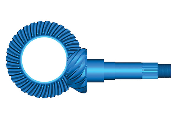
The diagram shows that the pin-ion is physically smaller when compared to the ring gear. As the ratio is numerically increased for a given size ring gear, the pinion must get smaller and is therefore weaker. This means that with the same size ring gear, a 2.73 gear set is stronger than a 4.11 gear set. Now, with this information in hand, we can verify the axle ratio in the vehicle or axle assembly. The easiest method is to have the axle cover removed and physically count the number of teeth on the ring and pinion gears.
Then take the number of ring gear teeth and divide by the number of pinion teeth. A ring gear with 41 teeth that meshes with a pinion that has 10 teeth yields 41 ÷ 10 or 4.10:1 axle ratio. This method is not always possible, and often a quick estimation is all that is required.
The typical automotive hypoid gear set has the pinion below the centerline of the ring gear. The axes of the gears are at a right angle to one another, and the ring gear is always the larger gear. (GKN Driveline)
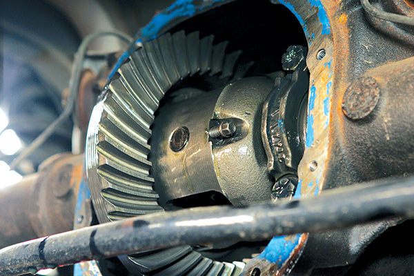
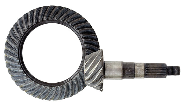
With the rear axle removed, you can see the ring gear and count the number of teeth. It is difficult, but you should be able to see the pinion gear behind the differential and count the number of teeth on the pinion as well.
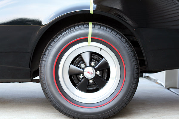
You can use chalk or simple masking tape to mark a tire reference point to the body. We chose the 12 o’clock position but any position works.
See Chapter 4 to determine if the axle has a limited-slip or open differential. If the axle has a limited-slip differential, raise both rear wheels off the ground. Place the transmission in neutral with the parking brake off. Mark the tire and fender.
Mark the driveshaft with tape or chalk. At this point, an assistant is very helpful. Slowly rotate the tire one full revolution while your assistant counts the number of rotations of the propshaft. Keep in mind that both rear wheels should be turning at the same speed and direction if you have a limited-slip differential.
The axle has an open differential if the opposite wheel is rotating in the opposite direction. In this case, lower the vehicle back to the ground and raise only one rear wheel off the ground. Rotate the raised wheel two full revolutions while your assistant counts the number of propshaft rotations. Your axle ratio is “number of propshaft rotations” to 1.
In Chapter 4, I stated that the following relationship described the open differential speed relationship.
2 x Ncarrier = Nleft + Nright
Now, Ncarrier is the same as the number of rotations of the ring gear. We want the ring gear to turn one full revolution and count the number of pinion or propshaft revolutions to get the axle ratio. Earlier I stated that [Input Speed ÷ Axle Ratio (AR)] = Ring Gear Speed. If we write this as:
Npinion / AR= Ncarrier
We can re-arrange the terms and get the following:
Ncarrier / AR= Ncarrier
Then just substitute the above result into the following equation for speed of the carrier (Ncarrier):
2 x Ncarrier = Nleft + Nright
We get:
2 x Npinion / AR= = Nleft + Nright
We held one wheel stationary by keeping it on the ground. The number of revolutions is zero. We turn the other wheel twice. This gives us the value on the right side of the equation: 2 + 0. So now we have:
2 x Npinion / AR = 2 + 0
Solving this equation yields:
Npinion / AR=1
Or, more simply:
Npinion = AR
Our assistant probably was not able to count exactly 3.55 revolutions of the propshaft. But we should be in the ball park and be able to tell the difference between 3.5 and 3.75 turns of the propshaft. With that information and the knowledge of typically available ratios for the axle in question, we now know the axle ratio.
Hypoid vs. Spiral Bevel Gear Systems
From a physical standpoint, there is just one main difference between the two different types of gears: In a spiral bevel gearset, the pinion centerline intersects the ring gear centerline. Also, the shape of a spiral bevel gear is normally conical.
The hypoid gear system has an offset or difference between the pin-ion centerline and ring gear center-line. This offset is given the variable E.
Most automotive applications utilize a hypoid gear system, meaning that the gears have an offset. Typical rear axles have a left-hand spiral angle on the pinion gear and a right-hand spiral angle on the ring gear to accommodate a below-center offset. A below-center offset allows the propshaft to be located lower in the vehicle relative to the axle shafts. This allows the tunnel in the vehicle to be shallower and protrude less into the passenger compartment. This pinion and ring gear spiral hand and below center offset arrangement are such that the pinion is thrust for-ward in the vehicle, or toward the head bearing, during forward-drive conditions. This is the main reason that the head bearing is typically larger than the tail bearing.
The spiral bevel gear is not commonly found in automotive applications, but this arrangement lines up the gears at a right angle to one another, as with the hypoid. The pinion centerline actually lines up with the ring gear centerline.
This offset increases the contact ratio of the gear system and provides more torque-carrying capacity. Con-tact ratio is a term used to describe the average number of tooth pairs that are in contact between the mating gears. Typical values for total contact ratio are in the 2.2 to 2.9:1 range (2.2 means that two pairs of teeth are in contact at all times, and a third pair is in contact 20 percent of the time). Also, hypoid gear systems are quieter due to this higher contact ratio.
This offset, however, has the negative side-effect of sliding friction at the tooth interface. This sliding generates heat and, without the correct lubrication, extreme wear known as scoring. As a result, extreme pressure (EP) additives are blended into the gear oil. This sliding also allows for lapping during the manufacturing process. Due to front propshaft/joint angles, front axles on four-wheel-drive vehicles require a right-hand spiral on the pinion; left-hand on the ring gear with an above-center offset. The typical machining tolerance range for the offset value for ring gears less than 12 inches in diameter is ± 0.001 inch.
Hypoid Mounting Dimensions
You need to consider four basic dimensions during the assembly of a hypoid gear set: shaft angle, offset, pinion mounting distance, and ring gear mounting distance. Only the latter two are adjustable during the assembly process.
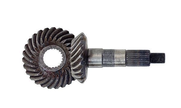
The hypoid gear arrangement has the vertical offset of the pinion in relation to the ring gear centerline. In a common automotive application, the pinion resides below the ring gear centerline. The pinion shaft also has ground diameters for the bearings, a spline, and thread to mate with the flange.
When fully assembled in the axle housing, the pinion has a head bearing that’s located near the toothed portion of the shaft. A collapsible spacer, tail bearing, seal, flange, and pinion nut follow the head bearing.
Shaft Angle
The shaft angle is measured between the pinion axis and the gear axis, which is represented by the Greek symbol alpha, α. A 90-degree shaft angle is common in automotive applications, is machined into the main axle housing, and is not an adjustable parameter.
It is important to recognize that even though this is not adjustable, there are situations where α may fall outside of the desired range. Typically if the shaft angle, alpha, is within 90 degrees + 0 degree 2’, – 0 degree 0’ (that is a range from 90.000 degrees to 90.033 degrees) the axle housing is fine. If the axle housing has been distorted or damaged and the shaft is outside of its range of operation, then the entire housing must be replaced.
Offset
Typically, offset is in the range of 15 to 20 percent of the ring gear outside diameter. The variable E rep-resents this (see top photo on page 93). Offset, like shaft angle, is not a dimension that can be changed once the axle housing is machined.
Even though the offset value can vary from one housing to another, most gear manufacturers utilize a common offset across all of the different gear sets that they produce. This allows for a common setup for tooling and checking fixtures in the manufacturing process. Hypoid gear ratios must be determined by tooth combination and not by relative gear diameters like helical or spur gears. Basing ratio on gear size will surely give you the wrong ratio.
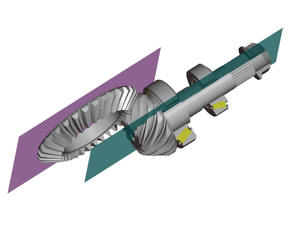
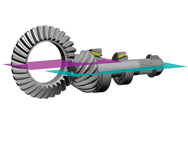
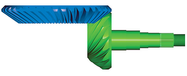
The symbol alpha represents the angle between the plane through the pinion centerline and the plane through the ring gear centerline. These planes (green and purple) need to be at 90 degrees to one another. (GKN Driveline)
When referring to offset, I am talking about the vertical distance of the pinion centerline with respect to the ring gear centerline. The green plane is below the purple plane, so we have a below-center offset. The pinion bearings are represented here; the pinion head bearing is always larger than the tail bearing. (GKN Driveline)
For example, Ford utilizes two common offsets. The 7.5-inch axles use a 1-inch offset while all of the others (8-, 8.8-, 9.75-, 10.25-, and 10.50-inch) use a 11⁄2-inch offset.
The only other Ford gear set with a unique offset is the 9-inch hypoid that features a 2.25-inch offset. This large offset is required to allow adequate clearance for the additional straddle-mounted pinion bearing in the differential case. Back in the late 60s and early 70s, the Gleason formulas that were used for quick calculations added approximately 10 percent more torque capacity to straddle-mounted pinions like this one. The significant offset provides a strength improvement. This design process has been updated significantly since then, and many other factors can be adjusted to achieve similar strength without requiring a straddle-mount bearing.
Coincidently, GM axles have a similar offset range. The 7.25-inch gears are at a 1-inch offset, while the 7.5-, 7.625-, 8.5-, 9.5- and 10.5-inch all have a 1.5-inch offset.
Pinon Mounting Distance
The pinion mounting distance is the distance from the back face of the pinion to the centerline of the ring gear. This is sometimes referred to as pinion depth, or checking depth, and is represented by the variable P. On most axles, this is adjusted with shims between the pinion head and the adjacent bearing.
Dana axles have the shim between the bearing cup and the axle housing. This shim provides the correct pinion position in the axle housing. Some of the newer Dana axles, like the model 60, have a shim underneath the head bearing and the cone. They have close to 0.080 inch total shim and spread it over the two locations. This helps to maintain the bearing race press-fit integrity.
Find more tips in the book: HIGH PERFORMANCE AXLES, DIFFERENTIALS AND DRIVELINES
Get your copy here!
SHARE THIS ARTICLE: Please feel free to share this article on Facebook, in forums, or with any clubs you participate in. You can copy and paste this link to share: https://www.cartechbooks.com/blogs/techtips/ring-and-pinion-gear-selection-for-optimal-performance
The bearing nearest the pinion head is referred to as the pinion head bearing because it is closest to the pinion head. This may sound intuitive but in vehicle position, the pinion-head is toward the rear of the vehicle, so this might be confusing. The pinion tail bearing is the bearing farther away from the pinion head.
Ring Gear Mounting Distance
The last basic dimension is the ring gear mounting distance. This is the distance from the back face of the ring gear to the pinion center-line. This dimension is typically not measured or specified directly. Instead, a total backlash, or the clearance between ring and pinion, is specified. This clearance specification makes certain that the ring gear mounting distance is correct, and that during heavy loading and deflection, the gear does not bind or run in “tight mesh.”
As mentioned above, as the axle ratio becomes numerically higher, the pinion head diameter gets smaller for a given ring gear diameter. Since the pinion head is smaller for a 4.56:1 ratio versus the larger 2.73:1 ratio, the ring gear mounting distance must be adjusted.
Ford uses a common differential mounting distance of 2.800 inches for the popular 8.8-inch axles, and accounts for the difference with thicker or thinner ring gears as required. This brings to mind Henry Ford’s saying about the Model T: “People can have the Model T in any color—so long as it's black.” You can have any ring gear mounting distance that you want, as long as it is 2.800 inches. This works out well since all of the Ford 8.8-inch differentials are common.
Unfortunately, the trade-off is that numerically higher ratios become thicker and therefore heavier. As the ring gear gets thicker, it becomes stiffer, and therefore deflects less. But as the ratio gets numerically higher, the pinion becomes the weakest link anyway, as it becomes smaller in size. This is why most vehicle manufacturers use a stronger grade of steel for the pinion as com-pared to the ring gear.
Dana and GM use different mounting distances based on ratios, and this led to the creation of GM term Series-2, Series-3, and Series-4 carriers. These are all for the 12-bolt passenger car axles; other variants are slightly different. For the 12-bolt (8.875-inch ring gear) differentials, the factory GM ratio range for a Series-2 carrier is 2.56 to 2.73:1 (the Series-2 differentials are the weakest, and the numerically low ratios are not common for high-performance applications), Series-3 is for 3.07 to 3.73:1 ratios and Series-4 is for 4.10 to 4.88:1 ratios. There are aftermarket gear ratios available for the different units that offer a wider gear ratio spread. If you measure the distance from the bearing shoulder to the ring gear mounting flange, you can deter-mine which series carrier you have.
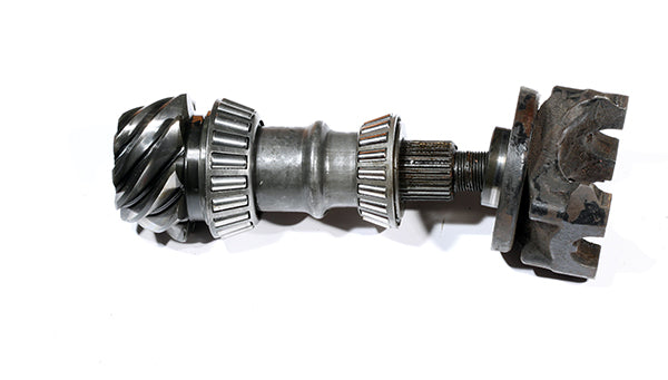
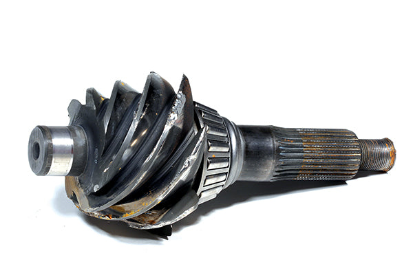
A pilot bearing along with the two tapered bearings support the pinion on the typical Ford 9-inch banjo-style axle so rigidity is increased. The tapered bearings resolve the thrust loads while the pilot bearing (left of the pinion head) resolves radial loads at the pinion head. This particular pinion is dam-aged and should be discarded.
When we are shimming the pinion in place, we are adjusting the pinion mounting distance. This is the distance from the back face of the pinion head (green plane) to the centerline of the ring gear (purple plane). (GKN Driveline)
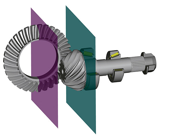
Even though we do not actually measure the ring gear mounting distance, it is the distance from the pinion centerline (green plane) and the back face of the ring gear (purple plane). It is much more practical and easy to measure backlash. (GKN Driveline)
This illustration of a 4.56:1-ratio gear set shows how thin the ring gear back face becomes and how small the pinion head is. This pinion has an outside diameter of 3.461 inches.(GKN Driveline)
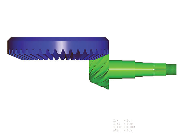
A 2.73:1-ratio gear set is illustrated here. The ring gear back face becomes thicker while the pinion head is larger when compared to the 4.56 gear set. This pinion has an outside diameter of 5.528 inches. Based on the larger pinion, this is a stronger gear set compared to the 4.56:1-ratio gears. (GKN Driveline)
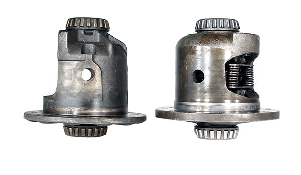
A Series-3 is on the right; the Series-2 differential case is on the left. The different ring gear mounting distances are compensated for with the differential cases instead of thicker and thinner ring gears.
The ring gears and pinions start off as billets and are forged into rough shape like these. The parts are recognizable as a ring and pinion but still require many more processes before it can go in an axle.
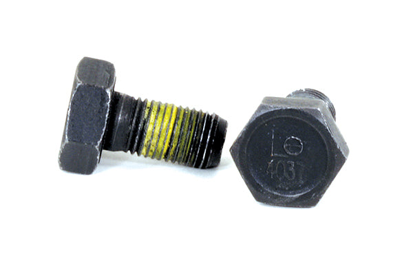
Left-hand-thread ring gear bolts can be found on some applications. Make certain that you carefully examine the head of the bolts for the telltale L or thoroughly research your application. Unfortunately, there are some left-hand-thread bolts that do not have the L on them.
Find more tips in the book: HIGH PERFORMANCE AXLES, DIFFERENTIALS AND DRIVELINES
Get your copy here!
SHARE THIS ARTICLE: Please feel free to share this article on Facebook, in forums, or with any clubs you participate in. You can copy and paste this link to share: https://www.cartechbooks.com/blogs/techtips/ring-and-pinion-gear-selection-for-optimal-performance
The ring gear mounting distance for Series 2 is 0.590 inch; Series 3 is 1.120 inches; and Series 4 is 1.325 inches. This is important to under-stand if you are going to change your axle ratio. It may require you to also change the differential.
Some people use a ring gear spacer and longer ring gear bolts to achieve the proper ring gear mounting distance. I highly recommend against this practice. The ring gear bolts provide a clamp load to resist the torque reaction between the differential case and the ring gear itself. Some axle manufacturers even add a bonding compound between the ring-gear-to-differential case interface to add more shear strength capability for higher powered applications. By adding a spacer, another interface is added into that load path, creating an additional joint in the structure.
Also, the longer bolts stretch more than the shorter bolts (they act like longer springs in the bolted joint situation), so less clamp load is realized for the same ring gear bolt torque. As the bolts stretch and relax under load conditions they can actually loosen over time. Some of the newer European applications, such as BMW and Mercedes, are starting to laser weld the ring gear to the differential case. This alleviates joint integrity concerns and allows for a thinner and lighter ring gear as the bolt holes’ thread depth is no longer required behind the ring gear teeth. Note that bolts are for service and disassembly but are not a requirement for assembly.
For stock applications, you may get by with the spacer arrangement. If you are transferring the torque from a high-performance engine through the axle, skip the spacer method and get the correct differential case. Most high-performance shops won’t even install ring gear spacers. I would never take the risk, but of course, I have seen the damage from ring gear bolts coming loose inside an axle. I like to refer to the carnage as a “yard sale” because the internal parts of the axle end up scattered all over the yard. This is very similar to what happens when a crankshaft breaks in your engine at 7,000 rpm. The GM 10-bolt (8.2- and 8.5-inch) and 12-bolt (8.875-inch), along with the Dana 60 axles, require specific differentials to account for the ring gear mounting-distance change with changed ratios.
Another factor to consider is that some ring gear bolts are left-hand thread. These are more common on front axles of four-wheel-drive vehicles. You must keep this in mind when rushing into disassembling an axle. Typically, the bolt head has the letter “L” marked on it. Some typical applications for left-hand-thread ring gear bolts are the GM 10-bolt 7.5- and 8.5-inch gears, GM 8.25-inch independent front suspension gears, and Chrysler 8.25-, 8.75-, and 9.25-inch gears to name a few.
Tire Size and Gear Ratio
As discussed earlier, the hypoid gears provide a torque increase and a speed reduction. There is another vehicle aspect that should be considered: tire size. If the tire size is decreased it, in effect, is like numerically increasing the axle ratio. If the tire size is increased, is like numerically decreasing the axle ratio.
Here is the basic equation to relate a change in tire size to effective axle ratio:
Axle Ratio = Engine Speed (rpm) x Tire Diameter (inch) x 60 (sec/min) x Pi / [Vehicle Speed (mile/hour) x 63,360 (inch/mile)]
Or:
Axle Ratio = N x D x 60 x Pi V x 63,360
Some people combine the constants of 60 x Pi ÷ 63360 and just use 1÷336 instead. You get the same result either way.
Here is an example:
Engine Speed = 3,000 rpm Tire Diameter = 28 inches Vehicle Speed = 70 mph
Which means:
Axle Ratio = 3,000 x 28/ 70 x 336= = 3.57
Now change tire size to 30 inches:
Axle Ratio = 3,000 x 28/70 x 336 = 3.82
Another method is to simply look at the percent change in tire size. From the example above, divide the new tire size by the old tire size and multiply by the initial axle ratio:
30/ 28 = 1.0714 x 3.57 = 3.82
So if you wanted to change to 30-inch tires and have the same performance as before, you would need to change the axle ratio to 3.82:1.
Another way to look at this is to calculate what the effective ratio would become if you did not change the ratio itself, but changed only the tire size. This would be the inverse of the above or:
28/30= .933333 x 3.57 = 3.32
Therefore, the larger tires have the effect of numerically lowering the 3.57:1 ratio to 3.32:1. Keep in mind that the actual ratio (3.57:1) has not changed; I am just trying to get an understanding of how tire size changes performance.
One last method is to use the following formula:
New Effective Gear Ratio = [New Tire Height ÷ Old Tire Height] x Old Gear Ratio
Use tire heights in inches. Note: It is best to measure the actual tire instead of what may be advertised on the side of the tire.
To estimate tire size, it is helpful to know how to translate the modern tire sizing convention into a usable size.
For example, a P255/60R15 tire has a 15-inch rim diameter. The tire width is 255 mm (divide by 25.4 to get 10 inches) and 60 is the aspect ratio or percent of the width-to-side-wall height. So this tire has a sidewall height that is 60 percent of 255 mm, which is 153 mm or 6.02 inches.
So, this tire height is 15 + (2 x 6.02), which is 27.04 inches; or simply plug your numbers into this equation (Fig. 6-1 below).
Of course, you can always use a tape measure to get the diameter, or at least a good estimate.
Find more tips in the book: HIGH PERFORMANCE AXLES, DIFFERENTIALS AND DRIVELINES
Get your copy here!
SHARE THIS ARTICLE: Please feel free to share this article on Facebook, in forums, or with any clubs you participate in. You can copy and paste this link to share: https://www.cartechbooks.com/blogs/techtips/ring-and-pinion-gear-selection-for-optimal-performance