The Different Types of Automotive Bodywork Jobs
This chapter looks at the core tasks used in damage and rust repair jobs, and at some of the most basic strategies and skills needed to master them. What you need to know starts here.

This tech tip is from the full book, AUTOMOTIVE BODYWORK AND RUST REPAIR For a comprehensive guide on this entire subject you can visit this link:
LEARN MORE ABOUT THIS BOOK HERE
SHARE THIS ARTICLE: Please feel free to share this post on Facebook Groups or Forums/Blogs you read. You can use the social sharing buttons to the left, or copy and paste the website link: https://www.cartechbooks.com/blogs/techtips/the-different-types-of-automotive-bodywork-jobs
Damage Repair
The analysis of crash damage is the first and often most critical step in repairing it. Before the 1930s, there was little or no literature avail-able to indicate standard operating procedures for this crucial first step in repair. While some practitioners body and fender men may have had fairly modern approaches to repairing deformed metal, most of them did not. They simply hit metal with hammers against dolly blocks and hoped for the best, and that everything would come out right. If metal was high, they hit it down. If it was low, they hit it up. In this process, they often inflicted terrible additional damage to metal, like stretching it and cracking it, but they managed to hide this damage under the filler material of that period, lead.
All of that changed in the early 1930s, when the Fairmont Forge tool company issued catalogs that contained the first easily accessible scientific information on sheetmetal repair. This methodical approach to repairing damaged autobody panels revolutionized the craft and trade of autobody repair. After a revision in the mid 1930s, this information was issued as a booklet of a little more than 100 pages, titled The Key to Metal Bumping, by Frank T. Sargent. In various formats, this book has been more or less continuously in print since then, with reprints of the 1953 edition still available.
This reprinted version of the 1953 edition of The Key to Metal Bumping is still available today. Its advice regarding the basics of analyzing collision damage and moving metal remains clear, to the point, and useful.

This damage is somewhat complex, and noodling the sequence of the event(s) that caused it is of medium difficulty. Still, the time taken to work out a theory of that sequence is well spent when you have to remove damage like this.

That book revolutionized auto-body repair by putting theory under it, and by specifying a series of standard procedures to guide it. It is, simply, the Holy Grail of sheet steel repair practice. While much about the autobody crafts has changed in the more than 75 years since The Key to Metal Bumping was first published, everything in it is still accurate, relevant, and useful. Anyone seriously pursuing the sheetmetal craft should examine a copy of this trove of body panel wisdom.
The nugget of The Key to Metal Bumping is that body damage consists of direct and indirect components. The first is deformed metal that is displaced beyond the elastic limit of the panel material, and that is holding the indirectly damaged metal out-of-place. Relieve the direct damage, the book advises, and the indirect damage will mostly spring back into its proper place. This is exciting because the area of indirect damage usually greatly exceeds the area of directly damaged metal. Unlocking the directly damaged metal is the key that enables you to solve the repair puzzle, usually with a great deal less intervention than might first seem necessary.
The Key to Metal Bumping divides direct damage into ridges, or outward bends and V-channels, which are concave, or reverse, ridges. Buckles and rolled buckles (added later to the damage vocabulary) involve metal that has been forced out of place, by surrounding metal as damage occurs. The book suggests that all direct damage can be described in the categories and characteristics of V-channels and ridges. As with all great theories, author Frank Sargent proposes a concept that is relatively simple but that explains much. He suggests that if you look at what appears to be complex panel damage, you can reduce it to combinations of the items noted above, ridges and V-channels. With the addition of buckles and rolled buckles, this theory becomes comprehensive.
Sargent proposes a method of working out damage that employs the least use of force, a novel concept at the time. Taking account of work-hardening factors, he advises working out the ridges and V-channels (mostly off-dolly) that represent direct and, to a lesser degree, indirect damage. When this is done, most of the rest of the indirect damage will be released. The panel will then return to its original, undamaged for-mat, or close to it. And yes, it is as simple as that.
Of course, a complex deformation or a series of deformations in a panel look anything but simple. Here, The Key to Metal Bumping offers a tremendously useful and (for the time) revolutionary concept of how to look at collision damage. It advises examining complex damage, and figuring out the order in which the metal was deformed; that is, the sequence of events in the collision that deformed it. Where was the panel first struck? Where did the striking force go next? What effect did the deforming metal have on adjacent metal, and how did that interact with the deforming force as it continued to deform the panel? This is, in its essence, a cause-and-effect theory.
While this kind of investigation may sound complex and difficult, it really isn’t. There are only so many possibilities for a sequence of events that produces collision damage. Items like paint scrapes and pressure embosses on metal provide excellent clues to the order in which damage occurred. With some experience, it becomes relatively easy to formulate a plausible theory regarding what deformed a panel, and in what sequence. Please note that such theories do not have to be perfect, but merely plausible and possible, to pro-vide the basis for corrective action.
Once a body practitioner has such a theory of damage in mind, The Key to Metal Bumping advises removing the damage in the reverse order of how it was created. In other words, you correct the last event in the damage sequence first, and work back to the first damage caused by the initial impact.
The reason for this approach is that, when it is followed, the best possible effort produces the best possible result. Taking damage out in the reverse order from how it was inflicted causes indirect damage to spring back, mostly without applying unnecessary and possibly damaging force to it. And, as they say on TV, “It really, really works!”
An Example of Simple Damage Repair
You can reduce complex damage, that is, damage that may involve multiple events and interrelated deformations of metal, to its simple components by using the type of analysis noted above. To make this work, you need to know how to correct simple damage. Let’s illustrate this process with a straightforward dent.
The dent in our example was made by a single impact against the hood. It cannot be determined exactly how the damage occurred. It may have resulted from an object like a tree branch falling onto the hood, or by the car being driven into a low-hanging object. It clearly occurred in one incident that resulted in a mostly straight dent, with a lateral crease at its center. This is among the simplest of all dents, and one of the easiest to remove.
The first step in correcting this damage was to determine its extent and boundaries. This was accomplished by outlining the obvious damage area with chalk lines, fol-lowed by lightly board sanding the damaged area, to more exactly define those boundaries.

Then, it was possible to see exactly where deformed metal existed, and to outline the damage with precision. While the preceding steps may seem a bit fussy, note that they yielded some very useful information: The damage area was actually larger than the first chalk line estimate indicated.
The best approach to removing this damage was to work out the crease in its center, the V-channel represented by line A-B, which was locking most of the metal in the dent out of place. Note that this was the first damage that occurred as the dent was created. Removing this crease had to be done in a way that did not upset or stretch the metal on either side of the crease, indicated by lines C and D, which was bounded by undamaged metal.
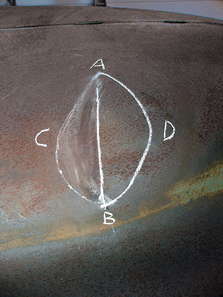
Step - 1:
This simple dent in the hood of a late 1940s Chrysler is about as basic as sheetmetal damage gets. It happened in a single incident. Other than pulling surrounding metal from the hood into the dent’s crease, there was little secondary damage. Relieving the center crease, without causing further deformation beyond the damage boundaries, is the challenge here. As the crease is worked up, caution is needed to not upset the indirectly damaged metal.

Step - 2:
Analysis of this damage is simple. An object impacted the hood along line A-B, creasing it and pulling metal in from as far away as lines C and D. Returning the metal in the crease A-B to its original position will release most of the indirect damage between C and D.
Step - 3:
Some board sanding revealed the exact limits of the out-of-place metal. The damage area was larger than the first chalk estimate indicated. Note that this is very heavy sheetmetal, between 20- and 21-gauge.

Step - 4:
With the board sanding completed, the size and shape of the damage area was confirmed. This had already been determined by feeling the metal but, in the planning stages of a repair, an accurate visual representation of damage is a more useful than a tactile one.
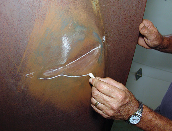
Step - 5:
The limits of the damage area were now redrawn in chalk. It was important to stabilize the metal along lines C and D, as repair force was applied to crease A-B. This prevented spreading the damage into new areas beyond C and D.

Step - 6:
The underside of the damaged area looked like this. Crease A-B is evident, and you can see a hint of line D, near A. Knowing where things are on the back side of this panel was critical, because this was where most of the force to repair it was applied.

Step - 7:
The deepest damage, near A, was worked up with a hammer-off-dolly technique. The dolly was alternated between supporting the metal along lines C and D, as the crease was worked up by hammering it on the underside of the panel.
Step - 8:
Here is a typical dolly position on line C, near A, for hammering up crease A-B. The dolly was used to prevent metal beyond line C from bulging out, as A-B was hammered up. It was critical to avoid upsetting the metal between A-B and C as this was done.

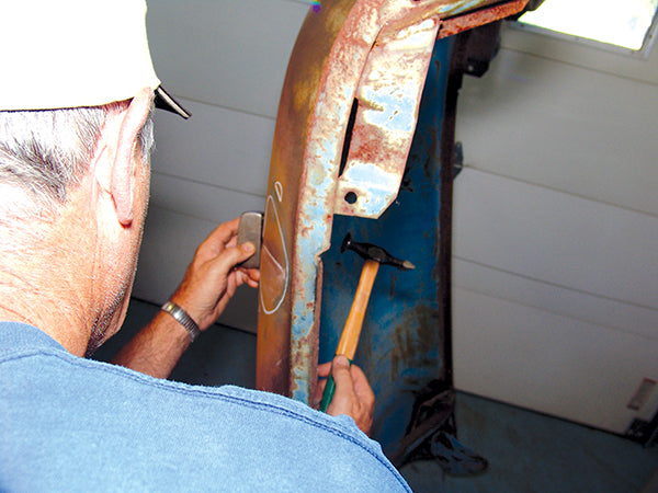
Step - 9:
From the back side, the hammering along A-B looked like this. Note the upright positioning of the hood to provide good ergonomics for working on this damage. There was plenty of room to swing the hammer and hold the dolly, and the access and position were comfortable for the metal man.

This tech tip is from the full book, AUTOMOTIVE BODYWORK AND RUST REPAIR For a comprehensive guide on this entire subject you can visit this link:
LEARN MORE ABOUT THIS BOOK HERE
SHARE THIS ARTICLE: Please feel free to share this post on Facebook Groups or Forums/Blogs you read. You can use the social sharing buttons to the left, or copy and paste the website link: https://www.cartechbooks.com/blogs/techtips/the-different-types-of-automotive-bodywork-jobs
Step - 10:
After the worst of the damage had been hammered up, it remained to level the metal in the damage area. A light shot bag was used to support the metal, as hammering continued. The shot bag reduced the chance that an accidental on-dolly hammer blow might stretch the metal.

Step - 11:
At this point, the damage area was again board sanded to indicate progress, and to see what remained to be done. This inspection indicated that while much progress had been made raising the crease, more metal in the crease area needed to be worked up.

Step - 12:
More hammering on the crease A-B was done, with the area immediately adjacent to the crease supported off-dolly. Note that much of the indirect damage had come up to level, and that the damage area had been greatly reduced.

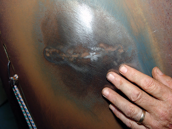
Step - 13:
The underside of the damage area was beginning to look much better. Very little of crease A-B or damage boundaries C and D remained visible. However, parts of crease A-B stubbornly remained.

Step - 14:
By now, surface deviations in the damage area had been reduced to no more than a few thousandths of an inch in depth. At this point, feeling the damage was as useful as, or better than, seeing it.
Step - 15:
The weapon of choice for raising the remaining low spots was a pick hammer. It can precisely move small areas of metal in very small increments, if you use it with concentration and patience.

Step - 16:
With pick hammering completed and its results confirmed by feeling the surface, a disc sander was applied to the formerly damaged area to level it and to indicate any low spots that may remain.

Step - 17:
After a little contouring with a flexible body file and some more disc sanding, the repair area looked like this. The hood could now be stripped, primed, and painted. No filler was needed in the repair area, because the metal was now level.

To accomplish this, a mildly crowned hammer was used to strike the back of the V-channel with a slap-ping motion, while a flat dolly block was held loosely against the metal under the hammer. The dolly was off-set to a location against the damage boundary, alternating between the sides of the dent, along lines C and D. The dolly block prevented the hammering force from inflicting further deformation beyond lines C and D.
After the major damage was hammered out, the dolly block was replaced with a small, handheld shot bag, to back up the area where lighter hammering was done.
At this point, most of the dam-age has been removed, and a great majority of the metal between lines C and D has sprung back into place, as ridge A-B was driven up. Some more hammer-off-dolly work, followed by board sanding, revealed the progress that had been made. Some depressed areas in the original crease remained to be worked out.
These low areas were raised with a pick hammer. This procedure involves lightly tapping them up, raising the depressed metal a few thousandths of an inch. Never get wild with a pick hammer because that will make a terrible, pocked mess of your work. Feel depressed areas with your fingertips, and raise them with a gentle touch with your pick hammer. The repair area was then disc sanded to indicate remaining low spots, and filed to level it.
Several of the previous steps (hammering-off-dolly, pick hammering, and filing) were repeated until the panel was level. The job took about 40 minutes, and resulted in a surface that required no application of filler material before it was painted.
This example of the removal of a simple dent illustrates the main features of this work. The damage was analyzed to determine how it had occurred, and removed in the reverse order of its occurrence. Care was taken to use as little force as possible during the repair. Removal of the main V-channel was accomplished in ways that minimized any possible stretching or upsetting of the metal, and that stabilized the edges of the damage area to avoid causing additional injury beyond them.
Of course all of this takes practice, and requires a feel for the metal and for what it is doing as you work on it. These processes are the basic ones used to remove dents. The principles behind them apply to all sheetmetal operations, including fabrications.
Small Rust Repairs
Repairing small rust-outs is one of the most common jobs in auto-body metal work. The first step is to determine the extent of the damage. This requires judgment: You do not want to remove serviceable metal from an original panel, but you also do not want to fail to go far enough to remove all of the diseased metal from a repair area.
Cleaning and probing a suspected rust area with a pick should reveal its extent. Abrasive blasting helps to expose the extent of damage, but runs the risk of warping the panel. While it is possible to clean metal for inspection with blast media like silica sand, silicon carbide, and aluminum oxide, it takes a very light application of these blasting media to avoid deforming and damaging a panel. That kind of restraint involves exercising terrific skill and judgment, but abrasive blasting can provide excellent cleaning. Glass bead blasting media should never be used on body panels because this stretches the side of the panel to which it is applied, and causes warping. Blast processes that use media like soda and plastic bead known as soda blasting and PMB, respectively clean metal without warping it, but not as thoroughly as harder blast media. Other processes that can accomplish good cleaning are dip stripping in heated chemical baths that employ electrolysis, and the application of various abrasive wheels.
Once the extent of rust damage is revealed, a repair strategy and repair material can be selected. In some cases, welding shut small defects (like pinholes) suffices, particularly if they are not in highly visible areas of panels, and if there are not too many of them. In other cases, replacement of large sections of panels may be required. These are judgment calls that depend largely on your skills and resources, and on what level of results you are seeking.
Probing with an awl is a good diagnostic technique. Delicate abrasive blasting also helps to reveal weak and potentially perforated metal. Areas like this wire-edged hood section are vulnerable to rust because they can trap moisture.

You can abrasively blast sheetmetal without damaging it, if you use combinations of low blast pressures, shallow nozzle angles, long nozzle-to-work distances, and abrasive-rich air/abrasive mixtures. Without taking these precautions, you can badly warp sheetmetal.

Don’t attempt to weld shut porosities and small holes on visible outer body metal. This approach is shown here, on a floor pan. It works because there are few holes, and the metal can be protected from further attack by corrosion.

This tech tip is from the full book, AUTOMOTIVE BODYWORK AND RUST REPAIR For a comprehensive guide on this entire subject you can visit this link:
LEARN MORE ABOUT THIS BOOK HERE
SHARE THIS ARTICLE: Please feel free to share this post on Facebook Groups or Forums/Blogs you read. You can use the social sharing buttons to the left, or copy and paste the website link: https://www.cartechbooks.com/blogs/techtips/the-different-types-of-automotive-bodywork-jobs
There is no option here. The large area of this panel, outlined in tape, has to be replaced with new metal. Trying to repair it would be a violation of the law of diminishing returns.

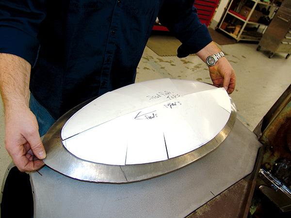
This paper pattern was used to check a complex shape: the top of a 1941 Willys fender that required sectioning. By cutting flaps into the paper, a three-dimensional pattern of the fender top was formed.
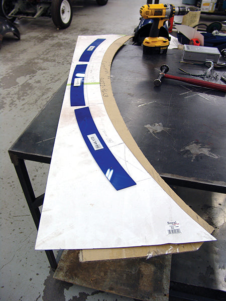
A contour template was created for the fender top. It was drawn on paper, using a set of standard body curves (the blue plastic pieces). Then, a paper template was transferred to cardboard. The cardboard template was used to check progress, as the fender top was being formed.
This scissors-like pair of pneumatic metal shears is one of the more unusual devices that can be used to cut sheetmetal. It works surprisingly well, if you can get the access room to maneuver it.

This is the panel patch that that was modeled earlier. Modern planishing hammers had origin in old, light-duty body shop power hammers used to smooth large panels. They are useful for stretching and forming metal.

A leather bag filled with lead or steel shot and a plastic mallet can do wonders forming contours in sheetmetal. Smaller shot bags are shown to the left of the one that is being used here.

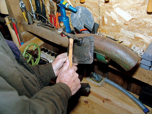
This blacksmith’s mushroom anvil, used with a medium-crown body hammer, allows very controlled forming of metal by stretching and shaping it.

This old tire-patching support device makes an excellent anvil for the shape that is being formed on it. Sometimes you can innovate with the tools that you use to form body metal.
If you opt to replace part of a panel, known as sectioning, there are several possibilities for securing the metal that you need. You may be able to buy a panel containing the section that you need from an original equipment manufacturer (OEM), or from an aftermarket supplier. You may have to find it as a salvage panel. Failing that, you may have to modify a similar panel, or fabricate one from scratch. In that case, you should choose sheetmetal stock that is similar to the material that you are repairing in type and thickness. It should also be material that you can form easily, but that holds its shape after it is formed.
If you have to form the section that you need from sheet stock, or to modify it from an existing formed piece, you need some method of patterning the original area, so that your section or patch conforms to it. There are many methods of patterning sheetmetal in three dimensions; some are very elaborate, while others are quite simple. Different situations may mandate using specific patterning techniques. In general, the simplest techniques are often the best.
There are many methods of cut-ting out metal that will be replaced.(The use of these tools, and forming patch panels, are discussed later.) The forming technique chosen to make a repair patch depends on the type of surface configuration that is required. Many fabrications for rust-repair patches employ relatively simple methods.
Small Patch Piece Welding Methods
There are three common methods for welding in small panel patches: oxy-acetylene, MIG welding, and TIG welding.
Oxy-acetylene, or torch welding, was once the dominant method for performing this work. It produced good results, but required consider-able skill, and produced enough heat around the welds made with this method to badly distort the surrounding metal. Correcting this distortion took considerable time and effort. The same was true of arc welding, a process that also was once used on sheetmetal, but that had tremendous drawbacks in terms of the skill required to perform it and the distortion that it inflicted on panels.
In the 1970s, metal inert gas (MIG) welding began to replace torch welding in body shops. MIG is a form of electric, or arc, welding. It requires less skill than torch welding, and produces far less panel distortion. It has become the standard method of welding autobody sheet steel in repair shops. Basically, this method feeds a continuous electrode, or wire, into the weld puddle, while shielding the weld area from high temperature oxidation with a neutral gas that flows through the welding handle nozzle, blanketing the weld area until it can cool a bit.
When the electrode wire strikes the welding target, it creates a short circuit that heats and melts the wire into the base metal. This creates and sustains a weld puddle. The heat melts off the end of the wire and breaks the short circuit, but the wire re-feeds into the weld, recreating the short circuit, and repeating the cycle. Another name for this phase of the MIG welding process is short arc welding, a term that describes the actual cycle of the process.
Today, MIG welders are compact, relatively inexpensive, and highly perfected. That is why MIG is by far the most popular method of panel welding in use today. However, tungsten inert gas (TIG) welding also has a distinct place in this work. On the upside, TIG welding produces the best welds and the least distortion of any welding method. Its advantages of quality are beyond dispute. How-ever, it requires considerable skill to perform, and TIG equipment is very expensive. It is also a slow welding process, as such things go, but TIG should be considered if ultimate welding quality is your goal.
Oxy-acetylene torch welding was the original method of joining sheetmetal panels. It produces satisfactory welds, but requires a high level of skill. Note that the welding rod is used to shield the weld puddle from the torch’s most intense heat.

This tech tip is from the full book, AUTOMOTIVE BODYWORK AND RUST REPAIR For a comprehensive guide on this entire subject you can visit this link:
LEARN MORE ABOUT THIS BOOK HERE
SHARE THIS ARTICLE: Please feel free to share this post on Facebook Groups or Forums/Blogs you read. You can use the social sharing buttons to the left, or copy and paste the website link: https://www.cartechbooks.com/blogs/techtips/the-different-types-of-automotive-bodywork-jobs
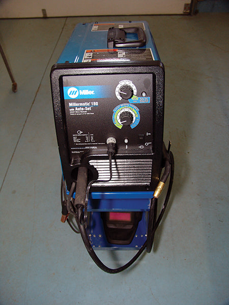
This MIG welding unit is typical of the high-quality modern welders that make it easy to do excellent panel attachment work, with very little heat distortion compared older techniques like oxy-acetylene torch and stick arc welding.
TIG welding requires expensive equipment and can be difficult to learn, but it creates terrifically strong joints with minimal heat distortion. When quality is paramount, TIG is the way to join sheetmetal panels or pieces.

From top to bottom are a butt seam, lap seam, and offset lap seam. If properly made, butt seams are best for appearance and durability. It takes some practice to make this joint but once you master it, you will be glad that you did.

In addition to choosing a welding process, it is necessary to decide what type of panel joint to use. Panel joints fall into three types: butt, lap, and off-set lap. Butt welded joints are by far the best. Lap welded and offset lap welded joints may seem easier to make, but are really more difficult. A properly fitted butt joint has a finished look on both sides; something that is critical when the underside of a repair patch may be visible. Also it doesn’t reveal its attachment point as it ages and is subjected to flexing and vibration. Lap welded and offset lap welded joints have a tendency to reap-pear in sheetmetal surfaces as they age, because the metal in them is double thickness and behaves differently than a consistent butt welded area.
Large section patches, like the rusted-out bottoms of doors, present the same problems as small patches, except that they have to integrate and look good in longer runs of metal and, therefore, must fit into larger curves and sweeps. This means that they can be more difficult to get right than small patches, even though the considerations in fitting them are similar to those for small area patches.
Patterning and forming small patch pieces is covered in more detail in Chapters 5 and 12. Similar techniques are used to form large patch panels. Many different approaches to patterning yield good results. You should choose a patterning technique that captures an appropriate level of detail, and that has sufficient accuracy for what you are fabricating. It should also be a technique with which you are comfortable, and in which you have confidence.
Materials used to make patch pieces should be similar to the metal that will surround them. This is absolutely necessary in the case of large patch pieces or panels. If a piece that is being cut out and replaced is 20-gauge metal, the replacement piece should match it in thickness. Sheetmetal described as 1018 and 1020 cold roll is about right for most forming operations used to create small patches and larger panel sections. These steels are also very suitable for welding.
Patch pieces and panels can be positioned for welding in many ways. Locking pliers, magnets, sheet-metal clips, and Clecos are among the most favored devices used to hold these panels in place prior to tack welding, and for welding them into final position.
Written by Matt Joseph and posted with Permission of CarTech Books
This tech tip is from the full book, AUTOMOTIVE BODYWORK AND RUST REPAIR For a comprehensive guide on this entire subject you can visit this link:
LEARN MORE ABOUT THIS BOOK HERE
SHARE THIS ARTICLE: Please feel free to share this post on Facebook Groups or Forums/Blogs you read. You can use the social sharing buttons to the left, or copy and paste the website link: https://www.cartechbooks.com/blogs/techtips/the-different-types-of-automotive-bodywork-jobs