
Performance enthusiasts typically have a desire to know and understand everything they can about the modifications they make to their engine, and with good reason. The deeper the understanding, the better the application of the component and or system. Besides, everyone likes to bench race once and awhile. Everyone knows the words “turbo” and “turbocharger” (except for certain spell check software makers who still insist that “turbocharger” is two words!). But most do not understand the internal components. Understanding the components and how they work together helps you develop a “feel” for turbos and aids in the service, communication, troubleshooting, and diagnosing of turbo failures. Imagine how successful you would be at hot-rodding your engine if you didn’t understand engine internals.
Typical turbocharger 90-degree section cutaway illustrates all internal working parts of the typical turbocharger. (Courtesy Diesel Injection Service Company, Inc.)


This Tech Tip is From the Full Book, TURBO: REAL WORLD HIGH-PERFORMANCE TURBOCHARGING SYSTEMS.
For a comprehensive guide on this entire subject you can visit this link:
LEARN MORE ABOUT THIS BOOK HERE
SHARE THIS ARTICLE: Please feel free to share this post on Facebook Groups or Forums/Blogs you read. You can use the social sharing buttons to the left, or copy and paste the website link: https://www.cartechbooks.com/blogs/techtips/anatomy-of-a-turbocharger-whats-inside-and-how-it-works
There are two primary components of the compressor: the compressor wheel and the compressor cover. Within these components there are many critical design types and specific features such as the diffuser, a critical feature that is typically designed into the compressor cover. Understanding turbocharger nomenclature and design features will help in future discussions about turbochargers relative to matching, system design, rebuilding, and failure analysis.
To begin a basic understanding of compressors, it’s important to review (or introduce!) some of the thermodynamic principals involved. While the field of thermodynamics is broad, perhaps one of the most important areas relative to turbochargers comes from within the first law of thermodynamics, the ideal gas law. Simplified, the ideal gas law states that the relationship between volume (V), pressure (P), and temperature (T) can be expressed as:
PV / T = Constant
Where P = pressure of the gas
V = the volume it occupies
T = the temperature of the gas
In simpler terms, if the volume is a constant, an increase in temperature results in a proportional increase in pressure. If pressure is constant, an increase in temperature results in a proportional increase in volume. Inversely, if volume is decreased, and pressure remains constant, temperature must decrease. Pressure and volume are directly proportional to temperature, and inversely proportional to each other.
The inner relationships of these properties in gases are ever present and put to use in everyday life ranging from refrigeration to how a diesel engine operates as a compression ignition engine. When applying the ideal gas law to turbocharger compressors, we can more easily understand how and why boost pressure becomes so hot and why dealing with this heat is important for proper tuning and maximum output.
Turbocharger compressors have design limits relative to how well they do their job of efficiently compressing the intake air. Each compressor has its optimum flow efficiency, maximum flow capacity (choke), and a pressure point where, below that, it will not flow at a given amount of mass or it will stall (surge). When a compressor is operating at its maximum efficiency within its flow range, that efficiency is expressed as a percentage of how close it comes to compressing the gas to meet the mathematical requirements of the ideal gas law. If a compressor was 100 percent efficient, then the compressor’s discharge temperature could virtually be calculated by knowing only the inlet temperature and discharge pressure. Such a compressor would be called adiabatic.
The term adiabatic literally means: occurring without gain or loss of heat. Therefore when a compressor is referenced as having a specific level of efficiency of say 76 percent; that essentially means it has the capability to compress air with a 76 percent adiabatic level of efficiency. The adiabatic efficiency of a compressor will never reach 100 percent however, simply because there are factors that add unwanted, but unavoidable heat. The acceleration of the air causes internal friction among the air molecules, the running contour clearances cause slip and imparts additional internal air friction, the air passing rapidly across the parts of the compressor wheel and cover cause heat from friction, and so on.
Different compressor designs carry different features that are designed around the efficient handling of the air as it’s compressed to allow that compressor to impart as little heat as possible and therefore raise its adiabatic efficiency. At the same time, the compressor has to be designed to efficiently have enough mass flow range to meet the range of airflow its engine requires. As a general rule, compressor mass flow is mapped to show flow ranges above 65 percent. Efficiency levels below that tend to impart too much extra heat into the air causing a variety of problems. If you’re turbo is running below this level, it’s time for a change!
The compressor wheel is perhaps the most commonly discussed component inside of a turbo. This may be because it’s the most easily understood, and because it’s the focus of the turbo being an air pump to begin with. The turbocharger’s compressor wheel is called a radial compressor because it takes in fresh air and accelerates it radially, or turns it 90 degrees, unlike axial compressors used in jet engines that accelerate air in the same direction it’s already going.
The compressor wheel has a number of critical areas, many of which are changeable within turbocharger model families, resulting in the various trims available to adjust flow parameters and correctly match the compressor to the engine. These changes must not be done by the turbo owner and must be done by the manufacturer at the time the turbo is manufactured. Changing these shapes by the turbo owner will destroy the design relationship between the compressor wheel and the compressor cover contour.
Most compressor wheels have been made from various aluminum alloys. However, there are more and more applications that push the limits of what the current aluminum alloys will stand. The higher the rotational speed of the aluminum, the shorter the life cycle. This is typically not a problem in most performance automotive applications due to the relatively low hours of operation. However, in some extreme high-boost applications, such as tractor pulling, this can pose a problem with wheel burst.

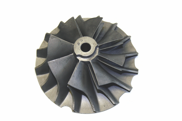
The compressor wheel has several important areas of design consideration: (1) inducer diameter, (2) tip height or tip width, (3) wheel contour, (4) splitter blade, (5) full blade, (6) backwall, (7) wheel diameter, tip diameter, or exducer diameter, (8) tip, impellor, or exducer, and (9) nose. (Courtesy Diesel Injection Service Company, Inc.)

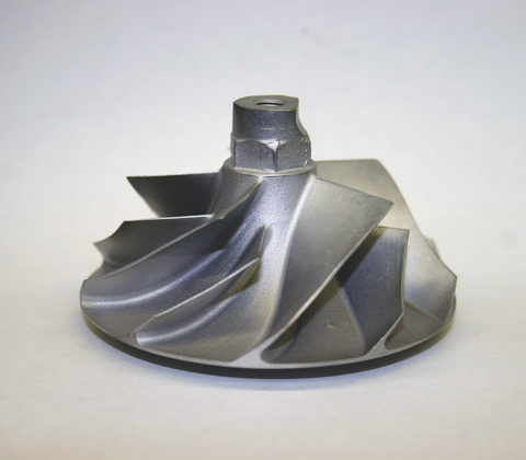
While most compressor wheels are a casting, this compressor wheel has been machined from billet. Careful examination of the wheel floor reveals the machining marks left after the formation of the wheel’s hub as the blades were made. This process is done by a five-axis milling machine and is used in special low-volume, high-durability, or high-performance applications where no production wheel will fit the intended need. These types of wheels are tremendously expensive but are justifiable in many instances. (Courtesy Diesel Injection Service Company, Inc.)

This compressor wheel has been cut in half. The shaft bore (1) typically runs all the way through the wheel, the compressor wheel hub (2) supports the blades and its shape forms the wheel floor (3) that turns the inlet airflow 90 degrees to make it a radial-type compressor. Some wheels will have an extended backwall (4), which strengthens the wheel at its highest point of stress for improved durability. The root of the blades (5) will have a small fillet to support the stresses of compression.
Compressor wheels are balanced on two planes: the nose and backwall. Note the balance stock removal off the nose and off the backwall in a process called scallop balancing. (Courtesy Diesel Injection Service Company, Inc.)
Special note: Any compressor or turbine wheel burst is an extremely dangerous situation and can be lethal. It is most advisable that a burst shield be employed in these extreme applications.
Some commercial diesel and performance racing applications are beginning to use titanium wheels machined on five-axis mills. While these wheels are extremely expensive, they do tend to solve some of the premature failures seen on highboost applications. In most cases however the cast aluminum alloys are more than adequate for most street and strip applications.
The compressor wheel is balanced on two planes: the nose and the back face. Because the wheels in the turbocharger rotate at such high speeds balance is critical for correct operation and life. The compressor wheel is set up on specially designed balance machines and the two planes of balance are defined. A balance spec is set by the manufacturer based upon turbo size and intended operational speed. Typically the balance spec is held to within hundredths of an ounce-inch. On extremely high-speed applications the rotor group can be dynamically balanced by stacking up all of the rotating components and indexing them, then balancing them all as a group. This is explained further later in this chapter.
There are many types of compressor wheel designs that have been used over the years. Each one has its own advantage and type of use. Care should be taken to understand the basics of each design to make sure that the turbo you intend to use for your application is of the type and variety that best suits your application.
Straight radial designs are not used much today. They develop high pressure but aren’t very efficient. When used in conjunction with a vaned-type diffuser the efficiency can be very high, but the tradeoff is a narrow flow range, which disqualifies it for use on an automotive application where the engine operates over a wide range of RPM. Historically they were used on diesel engines and generator applications that operate over a narrow RPM band.
A full-blade wheel is rarely seen and is typically on slower speed turbo applications. The full bladed wheel is not recommended for highperformance applications with high boost from high turbo speed. While the full bladed wheel is believed to produce a slightly higher pressure and has slightly higher efficiency, it tends to have trouble biting off enough air at higher speeds.
The splitter blade is the alternating shorter blade between each full blade. At higher speeds, the larger gap between the full blades is more capable of biting off more air. Once taken inside the compressor wheel, the splitter blade helps to efficiently manage and compress the air as it is accelerated and turned radially to the axis of rotation. The splitter blade is most commonly seen in automotive applications today.

The straight radial wheel is easily identified by the blades that emanate in a straight line perpendicular to the axis of rotation. They develop high pressures but are not as efficient or have as broad of a flow range as today’s wheel designs. (Courtesy Diesel Injection Service Company, Inc.)

The full-bladed compressor wheel means that all compressor wheel blades are full length rising from the max wheel diameter all the way to the inducer or inlet diameter of the wheel. (Courtesy Diesel Injection Service Company, Inc.)
The splitter blade wheel design is where every other blade is shorter than the full blade next to it. This allows for higher airflow at higher rotational speeds.

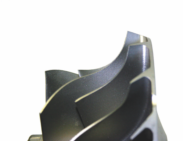
Backward curved impellor refers to that part of the blade element as it approaches the maximum diameter. Note how it curves backward relative to the direction of rotation, which is clockwise. This feature helps to begin air diffusion by slowing the air speed before it exits the wheel thereby making the airflow range broader in the higher efficiency regions of operation. (Courtesy Turbonetics)

These two wheels have nearly the same exducer diameter, but the wheel on the left uses a partial backwall while the wheel on the right uses a full backwall. You will almost never see a partial backwall turbo applied to a new application. (Courtesy Diesel Injection Service Company, Inc.)
The extended tip is a special machining process that cuts the compressor wheel impellor back at an angle greater than 90 degrees relative to the backwall. This allows for the rotational diameter to extend beyond the backwall diameter and makes a little higher pressure on a large diameter wheel while minimizing the wheel mass in the outer diameter. The moment of inertia is very sensitive the farther away from the center of rotation. (See Chapter 6 for moment of inertia specifics relative to mass at a given radius.) (Courtesy Diesel Injection Service Company, Inc.)

Eliminating the thru bore high-stress core of the compressor wheel reduces the risk of hub fatigue in a highly cyclical application and increases the compressor wheel life. A boreless design can last five times as long as a thrubore wheel. (Courtesy Honeywell Turbo Technologies)
The backward curved impellor or BCI wheel design, is the most common type of highly efficient compressor used today. This design creates a wider compressor map that is compatible with automotive applications and raises compressor efficiency by beginning air diffusion within the wheel before it exits into the diffuser of the compressor. The backwall of the compressor can be either a full backwall or a partial backwall. A full backwall is where the backwall is the same diameter as the overall diameter of the compressor wheel.
The idea of the partial backwall is to reduce the overall wheel mass allowing the wheel to be more responsive. However, most backward curved impellors cannot be properly supported without the aid of a full backwall, thus there are design tradeoffs.
A recent advancement patented by Honeywell Turbocharging Systems (Garrett brand) is the use of a boreless compressor wheel. The traditional compressor wheel has a shaft bore through its center that allows it to be fastened onto the turbine wheel and shaft assembly’s stub shaft.
The bore unavoidably passes directly through the area of greatest stress concentration in the wheel. This bore can cause a problem when the turbocharger is running at high rotational speeds, and of course, it goes through a high number of cycles, or accelerations. A single cycle can be a simple gear change where the turbo spools up then slows down for a gearshift, and then spools back up again. Aluminum alloy compressor wheels have a specific number of cycles they will last before fatigue sets in and the wheel bursts. For most automotive applications this does not represent a problem, but it does for commercial diesels. The higher the amplitude of each cycle, the fewer cycles the compressor can withstand. For example, a compressor wheel that regularly cycles on a given application from 40,000 to 80,000 rpm would last longer in-terms of cycles than the same wheel if used on another application where the cycles ranged from 60,000 to 110,000 rpm. In the turbo world anything that fails in less than 100,000 cycles is deemed a low-cycle fatigue problem. This is why other materials, such as titanium, are necessary in certain applications.
The compressor cover, like the compressor wheel, is typically made from an aluminum alloy. The compressor cover has several design areas to be noted. The nomenclature of these areas is important to proper communication as you seek help in choosing the correct turbo or while bench racing. If you intend to turbocharge your own vehicle, then you definitely want to know how to “speak turbo.”
The diffuser portion of the compressor is a critical portion of the overall compressor design. The diffuser is not an actual component, but rather the optimized path for the air as it leaves the compressor wheel on its way to the compressor cover volute. The function of the diffuser is to turn the rapidly compressed and high-speed air leaving the compressor wheel into static pressure as it fills the volute. Most diffusers used in automotive applications are the vaneless type formed by parallel walls between the compressor cover and the bearing housing face. The diffuser has to have a minimum diameter in order to have an effect upon the highly turbulent air exiting the compressor wheel. This is the reason the compressor cover outside dimension is typically so much larger than the outside diameter of the compressor wheel there has to be sufficient diffuser area. Most diffusers used in automotive applications are the vaneless type formed by the parallel walls between the compressor cover and the bearing housing face, or seal plate, depending upon the design of the turbo.
Vane-type diffusers are extremely efficient but have flow range restrictions and are therefore almost never seen on automotive applications. This goes back to optimizing efficiency within a specific flow range. While the vane diffuser does the better job in air diffusion at a specific match point, it becomes an impedance to flow rather quickly once the flow demand is greater than that compressor is optimized for. At higher rotational speeds, the slip angle of the air leaving the wheel tends to shift and can lose its optimum angle of incidence relative to each vane. The presence of the vanes will ultimately create a blockage of total mass-flow and therefore cause earlier compressor choke.
Compressor covers have an A/R rating, or area over radius relationship. However, compressors are not very sensitive to A/R ratios and therefore manufacturers seldom allow you to choose. The compressor cover A/R used to be adjusted more frequently when straight radial wheels were commonly used to shift the narrower compressor flow range to better match up with different engine ratings. The BCI-type wheel design basically does away with that tuning variation, leaving the compressor cover’s A/R rating as a relatively unimportant variable.
The inducer bleed is a ring cut around the inlet of the compressor eye or inducer diameter that allows an inlet bleed of air from the compressor wheel. This inducer inlet bleed helps to stabilize the airflow when the compressor is operating close to the surge point. In many cases a compressor can become unstable when it is operated close to its minimum flow at a given pressure ratio. The airflow can be rather choppy and become superheated causing the engine to run poorly. The inducer bleed helps to broaden the flow near surge and stabilize the airflow for smoother engine operation.

The compressor cover has four areas that can be easily seen from the outside: (1) the volute, (2) the discharge, (3) the eye or inducer, and (4) the inlet connection diameter.

From an inside view the following areas can be seen: (1) the compressor cover contour, (2) the cover inducer diameter, (3) the bearing housing connection, (4) the bearing housing pilot diameter, and (5) the parallel wall diffuser face.

A compressor cover cut in half reveals a better view of its design features machined into the casting. Air flows into the compressor inlet (1) where a bell-mouth flow nozzle is frequently formed to aid in the smooth air transition into the wheel. The inducer diameter (2) forms the limiting flow of the compressor and it is this diameter that is frequently regulated by certain racing bodies to limit turbocharger size and hence the engine’s power output. The compressor contour (3) cut into the cover matches the contour cut in the compressor wheel, but provides a typical running clearance of anywhere between 0.009–0.012 inch, depending upon model and use, but in some models the contour can be as much as 0.020 inch. The diffuser face (4) forms one side of the parallel wall diffuser. The bearing housing flange, or seal plate, forms the other wall once the turbo is assembled. The volute section (5) gathers the air as it exits the compressor wheel. Note how the cross-sectional area becomes larger as the volute approaches the compressor discharge because it gathers more air and the increased size slows the air helping to convert it from high-speed flow to static pressure.

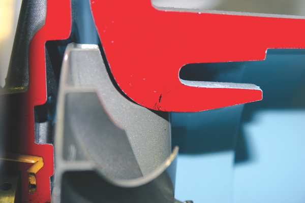
A close-up of an assembled turbocharger cutaway shows the parallel-wall vaneless diffuser that converts the highly turbulent air exiting the compressor wheel into static pressure. The diffuser face on the compressor cover forms one side of the diffuser while the other wall is formed by the seal plate or bearing housing flange. (Courtesy Diesel Injection Service Company, Inc.)

The vane type diffuser is superior in raising overall compressor efficiency, but it is restrictive and tends to inhibit compressor flow range. For this reason it is normally seen only on steady state or engines with a very narrow RPM operating range.(Courtesy Diesel Injection Service Company, Inc.)
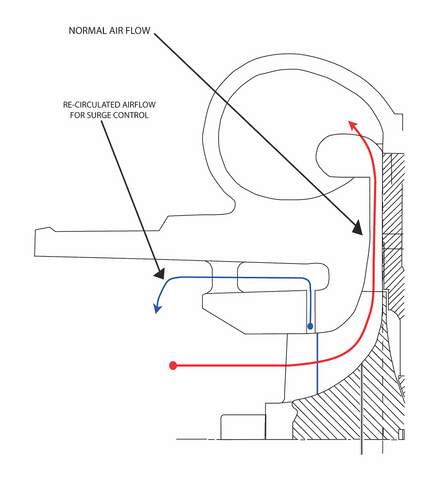
Inducer bleed shows how a small amount of the airflow is recirculated from the inducer back to the main inlet, thereby stabilizing the entire compressor stage when operated near surge. This design can also extend the max-flow range near choke-flow.

The benefit of a ported shroud compressor cover allowing more surge protection can be seen in this compressor map where two maps are superimposed showing the same compressor with and without inducer bleed. (Courtesy Honeywell Turbo Technologies)
Close-up of compressor wheel in its operating position relative to the mated contour cut into the compressor cover. Clearances allow for slight gyrations in shaft motion during engine operation without the wheel coming into contact with the cover at high speeds, which would quickly fail the turbocharger. (Courtesy Diesel Injection Service Company, Inc.)
This Tech Tip is From the Full Book, TURBO: REAL WORLD HIGH-PERFORMANCE TURBOCHARGING SYSTEMS.
For a comprehensive guide on this entire subject you can visit this link:
LEARN MORE ABOUT THIS BOOK HERE
SHARE THIS ARTICLE: Please feel free to share this post on Facebook Groups or Forums/Blogs you read. You can use the social sharing buttons to the left, or copy and paste the website link: https://www.cartechbooks.com/blogs/techtips/anatomy-of-a-turbocharger-whats-inside-and-how-it-works
Inducer bleed is a generic term that is also identified by the terms “map-width enhancement” and “ported shroud” compressor covers. Do not mistake this feature as one that will usually make a given compressor a good match if it wasn’t before. Inducer bleed is a development that mainly provides a slight amount of surge line movement, if any. Its real value is in stabilizing the airflow being supplied as you approach the surge point. Compressors all have slightly different characteristics. For example, a surge line for a compressor that was at 25 lbs mass at a 2:1 pressure ratio may have unstable airflow from 30 lbs down to the 25-lb surge point on the map. Engineering compressor maps, which are never shown to the public, will have this data on them (labeled “choppy air noise”). This assists the application engineer in avoiding an application where a given engine could enter this choppy air condition. Inducer bleed basically smoothes out this choppy area, and therefore in some cases does provide a bit more map width.
Inducer bleed is a loss mechanism however. The air that is bled out through the ring cut into the compressor cover from positive pressure is routed back into the compressor inlet and recirculates back to the wheel. This process induces additional heat because the air is slightly compressed more than once. This heat added lowers the compressor’s adiabatic efficiency. The volume of air flowing out of the inducer bleed ports is variable and is at its maximum as the compressor approaches surge. As the compressor extends further out onto its flow range the amount of air flowing out of the bleed port becomes less and will reach a static flow near the maximum efficiency area of operation for that compressor. As the compressor flow range extends further to the right from maximum efficiency, the bleed port can go from static to negative where there is actually additional air intake that will provide some extended flow.
In theory, if the compressor is well matched through dynamometer testing and flow measurement verification, and if that compressor was very stable near surge, inducer bleed would not be a recommended design feature due to the unnecessary reduction of efficiency and the added cost. But in reality there are several OEM cases when it does make sense when an engine’s air demand is just beyond where a given compressor will flow stable air. Additionally, aftermarket turbos applied without the aid of dynamometer testing and verification can be slightly mismatched. The double benefit of more surge margin and stability coupled with a slightly broader choke flow range makes sense.
Inducer bleed can cause a highfrequency noise as the blades of the wheel pass the interrupted openings that form the bleed ports. In some vehicles, where drivers spend their day listening to this high-frequency whine, it can become very annoying. Using Computational Fluid Dynamics, aerodynamists can go back and quickly design a full-bladed wheel that has the proper flow characteristics for that production engine, and the full blade wheel will then virtually double the number of blades passing the bleed ports, thereby doubling the frequency of the whine above an audible level. Problem solved!
So if you’re wondering whether a current production full blade wheel design you happen to see is something trick for your new gasoline project, think again. You’re still better off with a splitter blade wheel on a high-speed gasoline application. Besides, what high-performance enthusiast ever worried about turbo noise?
The contour cut into the compressor housing is matched to the compressor wheel. There is approximately a 0.009–0.012 inch running clearance between the compressor wheel and the compressor cover. Excess clearance causes a loss in efficiency while insufficient clearance can cause compressor wheel to compressor cover contact during operation, which will result in catastrophic failure. It should be noted however that a commonly misunderstood fact about today’s high efficiency compressors is that they can be rotated by hand and a slight contact between the inducer of the wheel and the eye of the compressor cover can be felt. This should not be call for concern. The oil pressure inside the bearing system will center the rotating turbine shaft and contact will not occur as long as the dimensions are correct.
New turbos are often built “dry,” without the benefit of engine oil. The purpose is to accurately measure end thrust and rotor tilt. The rotor is the term used for the assembled turbine wheel and shaft assembly with the compressor wheel installed. Placing a few drops of oil into the oil inlet of the bearing housing and rotating the rotor by hand will quickly allow the tolerances to reveal themselves as correct and wheel-tohousing contact will disappear.
In many ways, the turbine is the heart of the turbocharger. The turbine extracts energy from the exhaust to do the work turning the compressor wheel, which in turn, supplies air to the engine. So the turbine is where it all starts. The turbine has two principal components; the turbine wheel and shaft assembly and the turbine housing. Note that the turbine housing is called a “housing,” while the compressor cover is called a “cover.” This is intentional and is the correct nomenclature in the turbocharger industry. However, compressor “housing” is also correct. But under no circumstances should either be called a “snail!”
The turbine wheel and shaft assembly is commonly called the turbine wheel. It is the most critical and costly of all turbocharger parts. While it is technically an assembly, it can be thought of as a singular part, Manufacturers don’t sell turbine wheel and shaft components because the manner of assembly is not possible for the average person.
The turbine shaft is typically induction hardened in the bearing journal area only. This is for wear purposes. The shaft is ground to tolerances of around 0.0003 inch. For this reason, a tenths-reading micrometer is essential when doing turbocharger rebuilding.
On aircraft applications, the turbine wheel and shaft are all made from one piece as a fail safe dictated by the FAA. But in all other applications, the turbine shaft is welded onto the turbine wheel casting by either an electron beam weld or an inertia welding method. Most welds used in production today are the inertia weld type due to the speed of the production process it allows.
In most turbine shafts, the threaded portion of the wheel contains rolled threads instead of cut threads, which creates a stronger shaft once torqued with the compressor wheel in place. The reason is that the grain structure of the shaft metal is not cut but is compressed and therefore not weakened. A close examination of the threads on a turbine shaft will reveal smooth and shinny threads as opposed to the rougher cut threads typically seen on a machine screw.

The areas of the turbine shaft and wheel assembly include: (1) the exducer diameter, (2) the turbine wheel contour, (3) the turbine inducer or tip, (4) the seal ring, or piston ring groove, (5) the bearing journal or shaft bearing surface, (6) the stub shaft, (7) the turbine wheel, (8) the turbine shaft, (9) the shoulder, and (10) the rolled threads used to clamp the compressor wheel onto the shaft. (Courtesy Diesel Injection Service Company, Inc.)

A close-up of the turbine wheel and shaft assembly reveals the difference between the seal ring groove and the oil flinger, which is designed to throw oil away from the seal ring area during turbine rotation. (Courtesy Diesel Injection Service Company, Inc.)

Turbine shaft threads are rolled instead of cut to maintain material grain structure, which makes the threads stronger. When threads are cut, the grain is interrupted and the shaft is weakened.
There are knock-off turbochargers made in this big world that some will call counterfeit. Design aspects such as these escape the average consumer’s eye. Materials selection, manufacturing methods, and subtle design differences can make all the difference in a piece of machinery whose internal rotating parts can, in some applications, exceed the speed of sound! Buyers beware. I have to express my opinion here that some Pacific Rim turbo knock-offs are not a good way to spend your money. There are legitimate companies in this region that use genuine quality designed turbochargers from sources such as Garrett or Borg-Warner in their complete turbo kits. I am primarily referencing those that manufacture complete turbochargers, not kits, and sell them on eBay at low prices to uninformed turbo owners.
The turbine wheel is made from an investment casting process and is made from high nickel content materials such as GMR235 Super alloy or Inconnel 713C. “Inco” is typically desired due to its strength and higher heat resistance over the GMR235. However, you cannot select a turbo model and specify whether you get Inco or GMR235, each model is either made with one or the other. The GMR235 alloy is typically fine for most diesel applications, and even for many automotive uses. But high-performance gasoline applications typically use Inco for its higher heat resistance. If you’re building a high-performance gas turbo car, I recommend using turbos that have Inco turbine wheels. Those turbos marketed in automotive catalogs will tend to contain the correct material. However, in many highperformance applications, a largeframe turbo originally designed for a production diesel may have the necessary flow range you need, but its material may not be correct. Be sure to determine this often overlooked fact. Both diesel and gasoline highperformance applications will need Inco turbine wheels.
Schwitzer brand turbos have always used Inco as their standard turbine wheel material. If you’re contemplating a diesel turbo because of its flow range on your project, you would be wise to contact your nearest distributor and research the material used on the model you’re considering. As a general rule, if your turbine inlet is expected to rise near or above 1,400 degrees F, go for the Inco wheel.
In the turbine section, the turbine housing receives the most attention due to its part in tuning the turbo into the engine application. A given model of turbo may have a turbine wheel design that can accommodate several different turbine housings. The turbine housing is typically where the application is tweaked once the correct model is found. It’s important to know that the turbo model selected for your application has more than one turbine housing. Although the wastegate makes up for some degree of turbine mismatch, it’s a distinct advantage to know you have other turbine housing choices within the turbo model family you have matched to your engine.
While there are many specialty types of turbine housings, the two most common are divided and open housings. The divided housing uses a divider wall in the turbine volute to keep the exhaust path isolated from the exhaust port to the tip of the turbine wheel, or turbine inducer. This allows a maximum use of exhaust gas pulse energy, which sounds like a mouthful, but it’s actually very easy to understand. The engine is a reciprocating air pump. Consequently, the amount of energy during each exhaust gas pulse is greater than the amount of energy between each pulse. Similarly, if you placed your hand on the outlet of the shop air compressor you would feel rapid pulses. If you fill an air compressor’s tank and feel the air gun, you’ll feel a steady stream flow of air. A divided turbine housing allows each exhaust pulse to reach the turbine wheel tip and thereby transmit higher energy to the turbine.

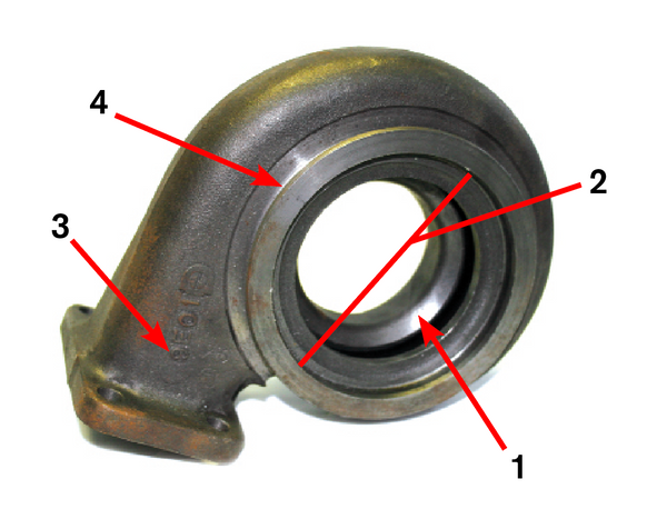
The external elements of the turbine housing that can be viewed include: (1) the turbine volute, (2) the turbine foot, and (3) the outlet connection (a slip ring type is shown). Sometimes the material type is shown, as in this case where it is made from ductile iron (note “DUC” on housing). (Courtesy Diesel Injection Service Company, Inc.)
Viewing the turbine housing from the bearing housing side we can more easily view the following: (1) the turbine housing contour, (2) bearing housing pilot diameter, (3) turbine throat area, and (4) bearing housing connection, which is typically a V-band or threaded holes for clamp tabs (V-band connection shown). (Courtesy Diesel Injection Service Company, Inc.)

While there are many types of turbine housing sizes and types, the two most commonly found are the tangential entry, open or divided type housings. Note the divider wall at the turbine gas entry point in the housing on the right. (Courtesy Diesel Injection Service Company, Inc.)

This turbine housing is cut in half perpendicular to the axis of turbine wheel rotation. The turbine wheel and shaft has been placed into the housing for perspective to help visualize the flow of exhaust gases as they enter tangent to the turbine wheel inducer tip. Note how the volute progressively has a smaller and smaller cross-sectional area. As the exhaust begins to exit the housing by way of the turbine wheel, exhaust energy is lost. The progressively smaller cross sectional area of the volute tends to create an even pressure all around the turbine wheel inducer tips to more effectively drive the turbine while stabilizing it in its dynamic path. The tongue of the turbine housing forces the remaining exhaust gas energy in the volute to exit the housing. (Courtesy Diesel Injection Service Company, Inc.

The A/R of a turbine housing may appear on the outside of the housing on the throat just beyond the turbine foot gas entry point as shown. (Courtesy Diesel Injection Service Company, Inc.)

On some turbine housings the A/R will appear just inside the gas entry above the turbine foot as shown. (Courtesy Diesel Injection Service Company, Inc.)
By contrast, an open housing has a more efficient and less restrictive flow, but doesn’t transmit pulse energy as well. Therefore a divided turbine housing is best employed on low-speed and midrange turbo matches where engine RPM is not high, but peak torque is more the desired result, such as in a diesel engine moving large loads on or offhighway. The open housing is typically used more on high-speed, high RPM automotive applications where exhaust becomes more steady stream flow. In a high-RPM engine, a divider wall tends to be more restrictive due to the additional surface area that causes losses with turbine gas flow. This is another design tradeoff where the optimum type of housing for a particular application depends upon how the engine is to be used.
The turbine housing is sized to optimize the pressure and flow as in the garden hose analogy. Turbine housings are rated in A/R. Many call this an aspect ratio. I’ve never liked that term (it is incorrect) and development engineers don’t use it. It’s simply the “A/R ratio.” The ratio is where “A” is the area of the volute at the tongue of the turbine housing. The “R” is the radius from the center of the axis of rotation to the centroid of the volute. The easiest way to think of the A/R is the swallowing capacity of the turbine. The larger the A/R is, the larger the swallowing volume. Therefore the smaller the A/R of the housing, the higher the pressure becomes in the turbine stage. Refer to the section Understanding Turbines in Chapter 3 for a more complete explanation of A/R ratios and how they should affect what turbo you choose.
This area of turbocharger design is one of the most frequently used, yet least understood relationships. In Chapter 3 I’ve tried to provide as complete of a definition as exists for better understanding of this portion of turbo design to help you more intelligently apply and communicate about turbos. The turbine A/R ratio is one of the most important variables and is a common necessary reference when it comes to tuning.
The turbine and compressor are machines supported by a common bearing system. The bearing system has many considerations that go into its design. The bearing system must allow for rotational speeds in excess of 100,000 rpm; it must also withstand shaft motion gyrations imparted onto the turbine shaft by the engine’s pulses at or near peak torque, handle radial and axial or thrust loads, withstand high temperatures, and contain enough imbedability of contaminates to keep the turbo from failing prematurely. Despite this fact, contaminated lube oil has remained the number one cause of premature turbo failure. The most common type of bearing system is the three-piece bronze bearing system that includes two journal bearings and one thrust bearing. The journal bearings are typically full floating and have specific clearances between the turbine shaft and bearing inside diameter, as well as the bearing outside diameter and the bearing housing bore. The two journal bearings typically rotate in relation to the bearing housing while the turbine shaft rotates in relation to the bearings. The bearings will typically rotate about one-third of turbine shaft speed, which divides the speed differential between the relative bearing surfaces to help minimize internal wear.
The third piece of the three-piece bronze bearing system is the thrust bearing. The thrust bearing has two bearing lands, one on each side. The oil enters from the center via a small oil galley and flows outwardly between the bearing surface and the thrust rings made from hardened steel held to very close tolerances.
Boost pressure acts upon the back face of the compressor wheel just as turbine pressure acts upon the back wall of the turbine wheel. This causes thrust load on the rotor assembly. When the pressure is greater in the compressor than it is in the turbine, it’s called a positive pressure differential. When the turbine pressure is greater than compressor pressure it’s called a negative differential. An engine will run best in a positive differential and a good turbo match will produce a positive differential at or near the designed match point. However, during hard acceleration, like in a drag race, the turbo will almost always be in a negative differential condition because the compressor boost can never keep up with the turbine pressure that is constantly rising. Once the vehicle is in a higher gear, the rate of change slows and the boost pressure should overcome turbine pressure. A positive pressure differential is desired for both power and economy.

The typical three-piece bronze bearing system design dominates the volume of production turbochargers. It consists of two journal bearings and a flat thrust bearing. Note the holes around the two journal bearings. These bearings are full floating, meaning that while the turbine shaft rotates inside the bearings, the bearings themselves rotate relative to the bearing housing. The thrust bearing is installed in a fixed positioned in a pocket inside the bearing housing. (Courtesy Diesel Injection Service Company, Inc.)
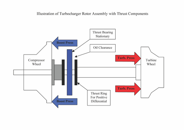
This illustrates how compressor and turbine pressures act upon the back face of each wheel in a typical turbocharger.

This close-up of a turbocharger bearing system shows what is called a separate fed, full-floating bearing system. Note the yellow colored oil passages that branch out to separately feed each of two journal bearings and the thrust bearing. In an end-fed bearing system, the main oil inlet will be positioned more centrally between the two journal bearings and will pass all the way through to the shaft. Oil will fill the center area and flow outwardly and lubricate the bearings from their ends. Note the snap rings that hold the journal bearings in place. (Courtesy Diesel Injection Service Company, Inc.)
Since the pressure on each respective side of the turbo acts on the back face of each wheel, the pressures tend to pull each wheel away from the other. The thrust surface for the compressor end is the bearing surface closest to the turbine and vice versa. This is a commonly confused issue, but important to understand. Most turbos will accommodate a maximum pressure differential of about 20 lbs of boost. If your turbo fails due to a pressure differential issue, it’s important to understand which surface is which.
Some turbo models will feature thrust-bearing upgrades because there may have been a larger compressor wheel developed later in that model’s life cycle. A higher load capacity thrust-bearing will tend to have a slightly larger bearing land and/or a ramp on the feed side of the bearing land that uses an inclined plane as a form of pump to improve oiling under high-stress conditions. That part would be called a ramped thrust bearing.
The oiling system can be separate fed or end fed in a two piece full floating bearing system. Following are the different types of bearing system used in turbos today.
Ball Bearings
While journal bearings are the most widely used in today’s turbos, ball bearings are coming onto the scene. Ball bearings that will withstand the hostile environment of a turbocharger are extremely expensive, but there are definite advantages. Ball bearings can entirely eliminate the thrust bearing, which accounts for approximately 40 percent of the bearing system drag on the turbo’s rotor assembly. Also, ball bearings reduce the viscous drag of conventional journal bearings and allow the turbo to spool-up approximately 15 percent faster than journal bearings. In any competitive application where it’s turbo car versus turbo car, ball bearings must be considered or you’ll be giving up too much to the competitor who is using them.
The graph on the next page shows a comparison between identical turbos on the same engine when accelerated from a 2,000-rpm start point on a 2.0-liter spark-ignition engine. If we analyze the graph closely we’ll find that the greatest separation between the ball-bearing and journal bearing performance comparisons is at about 0.4 second. That’s characteristic of the transient response challenge of turbos to come on boost quickly with rapid changes in throttle position. The journal bearing turbo jumps to about 42,000 rpm (700 Hz) while in the same 0.4 seconds, the ball-bearing jumps to 72,000 rpm (1,200 Hz). As the time passes, the differences in rotor speed tend to diminish as the journal bearing catches up. For this reason, all of the benefits from a ball-bearing system cannot be seen adequately on the engine dynamometer which takes data points at a steady state where speeds and load are stabilized. However, there are still benefits, they’re just more difficult to measure depending upon test accuracy. Championship race teams, for which Garrett originally designed the ballbearing system, claim that the reduction in power lost to the bearing system is up to 50 percent.

The Garrett ball-bearing system is contained in a cartridge assembly. The angular contact ball bearings totally eliminate the need for a separate thrust bearing, which reduces drag in the system. (Courtesy Honeywell Turbo Technologies)
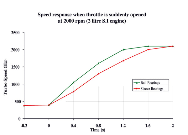
Turbine acceleration rate between journal and ball bearings is shown in Hz, or cycles per second, multiply values on the X-axis times 60 to convert to RPM. (Courtesy Honeywell Turbo Technologies)
The load capacity of a traditional thrust bearing is about 20Hg (inches of mercury). In high-boost, high-demand conditions this pressure differential can be exceeded and damage the bearing, causing turbo failure. Another plus for the ball bearing is its load carrying capacity, which is approximately 10 times that of the traditional journal and thrust bearing design. Certain conditions cause surges, and the ball bearing will better with stand the poundings than a traditional thrust bearing.
Ball bearing equipped turbos do not require as much oil volume as traditional bearings and will commonly come with an oil restrictor in the bearing housing oil inlet or contain a reference to a specific size orifice as a restrictor. Too much oil present will tend to negate some of the ball bearing advantages.
There is also what’s known as a hybrid bearing system, which uses one ball bearing and one journal bearing. Since there is a journal bearing, there is also a traditional thrust bearing. Consequently, the hybrid design carries most of the disadvantages of the journal bearing design. However, it should be noted that unless you are competing in a race class where ball bearings dominate, then traditional journal bearings operate just fine. Some enthusiasts just want the best, and crisp response is desired along with the horsepower that turbos help develop. Turbos have been blamed for being slow to react and the term “turbo” lag is well known. Turbo lag is usually a combination of factors that are caused by several things such as a poor match, bad manifolding, and spool-up time. Ball bearings will positively contribute to the elimination of turbo lag in a well-designed system.
Bearing Housing
The bearing housing is what supports the entire system and routes the oil to the bearings. Usually made of cast iron, the bearing housing can be air and oil cooled, or in many cases such as automotive use, it contains water jackets to allow for watercooling.
The bearing housing also houses all of the other small parts critical to turbo operation, such as the gas sealing system and oil control mechanisms. It also contains design features that insulate heat from the turbine from migrating into the lube oil and cooking it after engine shut down.

The turbocharger bearing housing is typically iron and houses all the bearings, seals, and connects the turbine and compressor ends together. Shown is the compressor end where one side of the vaneless diffuser is formed by the bearing housing flange (1). Also note the thrust bearing pocket (2), and the bearing bore (3). The compressor cover fits down over the bearing housing step (4). (Courtesy Diesel Injection Service Company, Inc.)

Looking at the turbine end of the bearing housing, there is typically a heat shield that covers the bearing housing portion where the turbine end journal bearing and seal ring are located. (Courtesy Diesel Injection Service Company, Inc.)
When any turbo system is installed, it must be done such that the bearing housing oil drain center is within 20 degrees either side of vertical. Otherwise oil can build up and leak either into the engine or into the exhaust and cause a severe oil smoke problem.
Except for the carbon face positive oil seals used in the turbos applied to carbureted engines before the widespread use of fuel injection, turbos don’t really have oil seals. Those early applications used the positive oil seals because the turbo’s compressor was subjected to vacuum frequently due to being applied to a throttled engine in what was known as a pull-through turbo system. The pull-through system referred to pulling the air through the carburetor as opposed to blowing it through. These two systems were debated frequently as to which was best because they each had their merits. But fortunately both are now passé, along with the carburetor.
There is what’s called a piston ring on both the compressor and turbine ends. The name comes from the fact that they look just like very small piston rings. Like piston rings, their primary purpose isn’t oil control, it is to seal the boost pressure and exhaust gas pressure from entering the oil drain cavity and consequently pressurizing the engine’s crankcase, an undesirable condition indeed.

A close-up of a cutaway section of the turbine end of a bearing housing shows some of the design features of a typical bearing housing and how it manages to keep the high heat from the engine’s exhaust from migrating into the oil and harming the bearing system. The backplate (1) divides the turbine area of the bearing housing surface from the turbine gases by creating a dead air space (2). The seal ring bore area is made in a casting portion that is suspended and creates a long heat path for the heat to travel (3). This gives the oil flung off of the turbine-end flinger an opportunity to cool it as long as oil is being supplied. The bearing bore is further isolated in its own portion of the casting (4) and not directly connected to the high heat area. (Courtesy Diesel Injection Service Company, Inc.)

The piston rings in a turbocharger are primarily dynamic gas seals that limit pressure, from either the compressor or turbine end, from entering the engine’s crankcase by way of the turbo’s oil drain cavity. The smaller one is typically used on the compressor end, while the larger ring is used on the turbine side. (Courtesy Diesel Injection Service Company, Inc.)

Once the oil leaves the thrust bearing area it is flung off at high speed. An oil deflector (1) shrouds the thrust bearing (2) and directs the oil to drain into the bearing housing drain cavity, thus keeping the area of potential leakage from being flooded with oil. (Courtesy Diesel Injection Service Company, Inc.)

The five major parts of a turbocharger include, the compressor cover (1), the bearing housing (2), the turbine housing (3), the compressor wheel (4), and the turbine wheel and shaft assembly (5). The rest of the parts, the bearings, seals, and oil control components are critical to the overall operation of the entire assembly. An understanding of these parts and their operation is helpful in the design and installation of a good turbo system, and is critical in turbo troubleshooting, maintenance, and rebuilding. (Courtesy Diesel Injection Service Company, Inc.)
Oil control is principally achieved by way of controlling the oil and deflection, which keeps the oil away from the areas of possible leakage. In a boost condition, oil cannot enter into the engine’s compressor or turbine due to the pressures in the respective housings. The oil that has drained away from the bearings is no longer under pressure and is subject to gravity to drain back into the oil pan through the oil drain cavity in the bearing housing. When a turbo is said to be leaking oil, it’s usually due to it idling too long, where there is no housing pressure to seal the oil away from the housings. That condition is called turbo slobber. Other conditions can exist that cause oil leakage and are covered in Chapter 10.
This chapter has discussed several different design variations of specific turbo parts such as turbine wheel material, different turbine housing availability, upgraded thrust bearings for high-load applications, etc. Trying to determine whether any of these options are necessary or even available for your model turbo can be difficult. One good way of obtaining this knowledge is from your closest turbo expert. There are many turbo experts who have years of experience and can help answer some of your questions.
Written by Jay K. Miller and Posted with Permission of CarTechBooks
