How to Build Racing Engines: Engine Build Tips
The engine assembly stage typically includes multiple mock-ups or pre-assembly stages where the fit and compatibility of all internal components is checked and verified. Care must be taken to prevent component damage during mock-up, fitment, and final assembly. Prior to final assembly, perform a thorough cleaning and layout of all engine components to eliminate the possibility of dirt contamination and to ensure that all components are present, spotlessly clean, and ready for assembly. To prevent mistakes due to distraction it is also important to have on hand and lay out all of the necessary assembly lubricants and sealers and the various tools required to properly assemble an engine. The following are typically required for most engines.
This tech tip is from the full book, COMPETITION ENGINE BUILDING.
For a comprehensive guide on this entire subject you can visit this link: LEARN MORE ABOUT THIS BOOK HERE
SHARE THIS ARTICLE: Please feel free to share this post on Facebook Groups or Forums/Blogs you read. You can use the social sharing buttons to the left, or copy and paste the website link: https://www.cartechbooks.com/blogs/techtips/how-to-build-racing-engines-engine-build-tips
- Torque Wrench
- Ring Compressor
- Dial Indicator
- Dampener Installation Tool
- Rod Bolt Stretch Gauge
- Cam Installation Tool
- Engine Assembly Oil
- Engine Oil
- ARP Ultra-Torque Lube
- Anti-Seize Compound
- Loctite Thread Sealant
- Loctite Threadlocker
- RTV Silicone
- Carb Cleaner
- Brake Cleaner
- Thread Tapping Lube
- ARP Thread Sealer
- Non-lint Paper Towels
- Magnifying Glass
- Engine Stand

Engine building requires attention to small details such as installing pin oiling jets in the main bore saddles prior to assembly. These preliminary preparation steps are often essential for maximum power and durability.

Proper engine assembly tools help maintain focus while building a racing engine. For this build we’re using a selection of engine building tools from ARP, Comp Cams, Proform, Snap-on, and Summit Racing. They include a set of micrometers, a cam installation tool, universal cam checking tool, digital scale, rod balancing tool, valvespring-height mic, digital calipers, electric piston ring filer, and deck bridge.

Dart’s Big M Sportsman block features siamesed 4.600-inch bores and 9.800- inch deck height with ductile iron four-bolt main caps, priority main oiling, minimum .300-inch wall thickness, and clearance for up to a 4.500-inch stroke.


A rotating adjustable engine stand with 360-degree cranking head plate from Summit Racing makes it easy to adjust a block to any desired position without requiring the usual large pry bar to rotate the engine.
Assembly Procedure
Our sample engine build is a 565-ci big-block Chevy based around a Dart Big M cylinder block and Dart Big Chief Pro 1 aluminum cylinder heads. Following the step-by-step procedures is designed to simplify the mating of all the important components.
Oil Gallery Plugs
After thoroughly cleaning the cylinder block and all of the individual engine parts you are ready to begin the final stage of engine assembly.
Begin by installing the oil gallery plugs. Every engine is different, so be sure to identify the correct plugs for your particular engine.
Apply a small amount of ARP Thread Sealer to each plug and install it snugly with a hex key wrench. At this time you may also want to install the core plugs in the cylinder block. Apply sealer lightly to each core plug and drive into the appropriate openings.

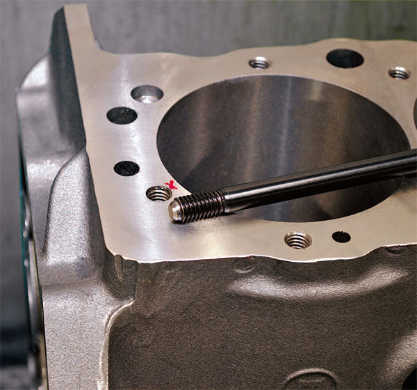
The initial step in block preparation includes chasing all threaded holes with thread-chasing taps from ARP. This is particularly important to ensure proper seating of main cap and cylinder head studs.

Check the depth of all head bolt holes to ensure adequate depth when head bolts are being used. Too little clearance can prevent proper clamping and initiate a blown head gasket.
Cam Bearings
Carefully install the camshaft bearings. Our sample big-block Chevy is fitted with Comp Cam’s Composite Coated cam bearings. To help start the cam bearings, the cam housing bores were pre-chamfered with a 2½-inch ball hone attached to a drill motor. Carefully align them and drive them in place.
Main Cap Studs
You can upgrade to ARP main cap studs for added crankshaft stability. To maintain proper fitment Dart recommends that the main caps and block mating surface be lightly deburred upon removal to ensure that the correct main size is maintained.
To check the work, run a straight-edge through the housing bores and check all of them with a dial bore gauge prior to removal. These measurements are then compared to new ones taken after the main studs were installed and torqued. The goal is to maintain the proper housing bore measurement and the existing housing bore alignment. In our case, Dart’s precise main cap fit allowed us to make the swap with no misalignment.
This tech tip is from the full book, COMPETITION ENGINE BUILDING.
For a comprehensive guide on this entire subject you can visit this link: LEARN MORE ABOUT THIS BOOK HERE
SHARE THIS ARTICLE: Please feel free to share this post on Facebook Groups or Forums/Blogs you read. You can use the social sharing buttons to the left, or copy and paste the website link: https://www.cartechbooks.com/blogs/techtips/how-to-build-racing-engines-engine-build-tips
Main Bearings
Install the grooved upper main bearing shells into the block and verify alignment of the bearing insert oiling hole with the priority main oiling hole in each main web housing bore. Some builders grind the opening to match the bearing insert if the hole is partially blocked by the bearing being misaligned.
On our build the bearing feed hole did not exactly match the opening in the block, but once the feeder grooves were cut for the pin oiler inserts, it all matched up correctly.
Install the lower half-shells (ungrooved) in the appropriate main caps.
During initial engine mock-up, the proper clearances were determined, and a combination of standard and 1-under Calico coated main bearings were used to achieve .003-inch clearance. Although we are using Calico coated engine bearings for added protection, high-pressure assembly lube on the bearings for the crank installation is still used.

Some builders are careful to countersink the head-bolt holes after decking and surfacing to prevent misalignment and/or cracking.

Carefully deburr the bottom of the cylinders after honing to remove sharp edges.

The upper main bearing is always grooved. Inspect the back of the bearing for dirt or damage, then install it in the housing bore, pressing it down firmly by the parting lines. Install the ungrooved mate in the main bearing cap.

ARP instructs that main studs and the corresponding threaded holes in the cylinder block be thoroughly cleaned. Then install the main studs finger tight. Do not overtighten them. If the studs do not fit properly, chase the threads with an ARP thread-chasing tap.

A convenient place to check the crankshaft thrust is off the rear main crank throw adjacent to the thrust bearing. Rig a dial indicator horizontally and zero it at the top. Then use a pry bar to move the crank forward and backward to check the thrust. This crank checked at .0075 inch.
Once the bearing’s shells are properly seated in the housing bores, apply lubricant and set the crankshaft in place. Rig a dial indicator to read off the front of the crank snout or from one of the crank throws and check the crankshaft thrust clearance.
Crankshaft
After numerous mock-ups with setup bearings, the crank is usually contaminated. Clean it using small Moroso cleaning brushes available from Summit Racing. Brush all of the oil passages thoroughly. A common trick is to stand the crank upright in a rack and spray it down thoroughly with brake cleaner. It leaves no residue and the journals can then be wiped carefully with soft, shop (blue) paper towels that don’t shed.
When you are satisfied that the crank is clean, install the rear main seal. If you have a two-piece seal, clock one half of it in the block so that one side protrudes by about 3/16 inch. Lubricate the upper main bearings and carefully lower the crank in place.
Clock the other half of the rear main seal in the opposite direction in the rear main cap, apply a thin bead of sealer to the parting faces, and carefully work the seals together as you install the cap.
Apply assembly lube to the lower rear main bearing and install the rear main cap. Torque to recommended specs and turn the crank to ensure that it spins freely.
Install the lower main bearings in each of the other main caps using assembly lube for lubrication. Torque all studs to spec and check the crank for freedom of movement.
Camshaft
Lube the cam bearings and carefully slide the camshaft into the cylinder block taking great care not to scratch the cam bearings or nick the lobes on the block. For best results use a camshaft installation tool like those sold by ProForm. These tools bolt to the front of the cam and provide a cushioned handle that offers additional leverage so you can guide the cam easily into the block.
Break-in motor oil is used for a lubricant because this particular engine has a roller camshaft. Flat-tappet camshafts normally require the application of a special camshaft break-in lubricant to the lifters and cam lobes to protect them upon initial engine startup. Many builders wait until the very end to install the rear cam plug, but it is better to install it early on to prevent accidental contamination via the exposed rear cam journal. Most engine stands permit this.

The reciprocating portion of our power system is a formidable combination that includes Ross Pro Mod Nitrous pistons with high-strength pins and pin buttons, scat H-beam connecting rods, Calico coated rod bearings, and Speed Pro HellFire piston rings.

Even lightweight big-block cranks like this Scat Pro Comp unit are heavy and difficult to handle. To minimize the chances of damage, have an assistant help lift the crank and lower it carefully into the main bearings.
Cam Drive
Belt drives are the preferred cam drive device for most racing applications. They deliver rock-solid timing and are very durable. Care must be taken to provide proper camshaft thrust clearance and proper belt alignment by making sure that the crank drive pulley is fully seated against the shoulder on the crank snout. The lower pulley incorporates drive guards to prevent belt walk.
When properly aligned, the belt runs true with minimum drag.
Cam timing adjustments are performed by loosening the six bolts on the upper pulley and using a locking lever to hold the cam still while the crankshaft is rotated. This rotates the upper pulley in relation to the camshaft, altering their relative position and thus the actual camshaft timing. Only very minute movement of the crank is required to effect a 2-degree advance or retard of the camshaft. The drive permits up to 10 degrees of advance or retard, but if it takes more than 4 degrees, you probably have the wrong cam.

A ProForm cam installation tool provides a sturdy grip and the necessary leverage to carefully guide the cam into the bearings without damaging them.

The Dart block requires .300-inch-taller lifters. Note that the lifter tie bar installs to the inboard side toward the valley.

ARP makes a stud kit for Jesel-equipped Chevy belt drives. It works just fime with Comp belt drives too.

Big-block Chevy drive uses an idler pulley to maintain tension and promote stable timing. When the upper pulley (red) lock nuts are loosened the cam remains stationary while the crank position is altered as required.

Cam thrust on the Comp Cams belt drive is adjusted via three inclined ramps with corresponding ramps on the cover plate. As the plate rotates, cam thrust is increased or decreased depending on the rate of ramp incline.

When the desired amount of cam thrust is set, an indicator mark is placed at the top and the three button-head screws lock the cover in place. Multiple holes allow for an infinite range of cam thrust adjustment.

Adjustable pointers like this Moroso unit can place the timing indicator in the exact proper position for accurate timing adjustments.

Check out ProForm’s timing pointer with built-in timing light.

The cylinder bores are finished to .008-inch piston-to-wall clearance with 200-grit, then 280-grit, and finally 400-grit.

A ProForm digital scale is essential for accurately weighing pistons, pins, piston rings, rods, bearings, and other components for balancing.

A Summit Racing tapered ring compressor allows easy ring installation.

Precise piston ring gapping is easily obtained with a ProForm electric ring filing tool. Piston rings are clamped in place on the sliding ring platform and the handle is used to guide the ring end against the grinding surface. A dial indicator shows the amount of material being removed.

ProForm’s connecting rod balancing jig uses the ProForm digital scale to accurately obtain rod balancing weights.

The sliding ring support platform has an adjustable cam and a locking device to help position the ring end face perfectly parallel to the grinding wheel surface.

A ProForm deck bridge makes quick work of checking piston deck height.

Rod side clearance on our sample big-block was measured at .021 inch.

The ARP rod bolt stretch gauge indicates .0065-inch stretch as recommended by ARP.
Pistons and Rings
File fit rings are always used on racing engines. They permit the most precise ring end gaps for maximum sealing. An electric ring filing tool such as that made by ProForm is recommended. The tool allows you to lock the ring in position so the end face is square to the grinding surface. Then the sliding mount platform allows you to move the ring against the grinding wheel while a dial indicator shows the amount of material you have removed.
Square each ring in its respective bore and then use the ring grinding tool to achieve the correct end gap. Once the rings are properly gapped, assemble them onto each piston carefully. Most builders gently twist them on by hand.
In our sample big-block, the Ross pistons use pin buttons to hold the piston pins in the pin bore. Once the piston is installed, the buttons are captured in the bore, providing the proper end clearance as preset during engine mock-up. In this type of assembly the pin buttons are added last, just before the assembly is inserted in the cylinder bore.
We used a Summit Racing tapered ring compressor to compress the ring pack to the proper diameter to slide into the bore. With the crank properly positioned, the assembly is easily pressed down in the bore until the rod bearing insert is guided carefully onto the rod journal.
As each piston is installed, lubricate the rod journal and install the rod cap with the appropriate bolts. Some builders torque each pair of rod bolts as the pistons are installed. Others pull them up snug and then set the proper bolt stretch on each individual bolt. Use an ARP rod bolt stretch gauge to measure the bolt stretch.
Measure the static length of each rod bolt and then slowly tighten each bolt until the recommended stretch is obtained. In this case we strived for .0065 inch using ARP Ultra Torque lubricant on the threads and mating surfaces.
Oil Pump and Drive
Many builders install the oil pump, drive, and oil pan at this point, but this may not be the best practice since it is still possible that some small component might be accidentally dropped down the distributor hole or the camshaft gallery. This requires removing the pan to retrieve it. On our example a block-off plate on the rear main cap oil pump mount was installed since a dry sump system is being used. Then the oil pan was installed and the appropriate precautions on the top of the short block were taken to prevent accidental transfer of small parts to the pan. A cork in the distributor hole and tape over the cam and lifter gallery did the trick.
Since the dry sump pump and attending drive hardware require considerable setup, the short block was finished and then we concentrated on fitting and plumbing the dry sump system with appropriate consideration for the chassis fitment requirements. This engine uses a Jegs front motor plate for chassis placement, so mounting the dry sump pump was problematic until the appropriate opening in the plate was measured and cut to provide full movement of the pump assembly and attending hardware.

Small-diameter (6¼ inch) BHJ dampener for internally balanced applications features internal elastomer construction for optimum damping properties. The dampener must be honed for a .0015- to .0020-inch fit.

The Moroso dry sump pump and drive mandrel must accommodate the dampener, crank trigger, and a Weiand Action Plus water pump. Front block plates add dimensional complication to the setup. Drive belt must run straight and true via guides on the drive mandrel.

Instead of installing an oil block-off plate on the rear main cap for dry sump systems, some builders tap and plug the oil feed gallery in the block.

Plumbing your dry sump and fuel systems is easy to accomplish with high-quality stainless braided hose, nickel plated fittings, and AN wrenches from Jegs Performance Products.

With Moroso pump and dry sump pan installed setup plumbing begins with trial fitment of nickel plated AN fittings and braided hose from Jegs Performance. A combination of 45-, 90-, and 120-degree fittings normally accommodate most chassis fitment requirements.

Nickel-plated hose fittings from Jegs provide superior protection against galling. After lubing the inner hose and applying anti-seize to the threaded fitting, place the fitting in a set of Jegs protective vise guides and tighten the fitting with the appropriate-size Jegs AN wrench as shown.

With the Jegs motor plate installed, mock-up essential plumbing like this CV Products remote oil filter mount with a Wix race filter.

Moroso’s dry sump tank is positioned to accommodate hood clearance and still provide gravity feed to the Moroso dry sump pump.

Koul Tools braided hose assembly kits from Jegs Performance incorporate assembly guides for all popular hose sizes. With hose fittings placed inside the split assembly guide the tapered cone reducer guides the hose into the fitting without interference or personal injury from frayed braided hose ends.

Motor plates also require precise fitment of the crank trigger ignition pickup. Spacers are used to position the pickup mount. The pickup flange incorporates two mounting positions to make precise alignment easier with a wide variety of setup requirements.
Dart recommends machining a .150- by .350-inch bullet to center each head stud.

T&D precision rocker arm installation begins with the rocker setup tool. Shims are adjusted under each rocker stand until one end of the gauge fits squarely on top of the lash cap when the other end just touches the bare setup shaft setting in the rocker-stand cradle.

The MLS (multi-layered steel) head gasket incorporates embossed layers with flat inner layers to provide the seal.

Ross Pro Mod nitrous pistons use inboard bosses with shorter, lighter pins and pin bushings with oil ring grooves to locate the pins and support the oil ring where the pin bore extends into the oil ring groove.

When T&D rockers are properly installed this proper geometry is achieved. Include the lash cap if using titanium valves. Roller is positioned slightly inboard of the valve centerline to provide proper motion. Note the adjustment shims underneath the rocker stand.

Measure the skirt diameter on Ross Racing pistons with a ProForm 4.00- to 5.00-inch micrometer. Ross and other manufacturers specify the exact location where the piston diameter should be checked.

Fel-Pro’s #1077 MLS head gasket features .041-inch compressed thickness. Note precise fit to cylinder bore.

The Dart Big M block and Big Chief head employs two inner head studs per side to ensure even clamping force.

An important part of the engine-building process is providing the right auxiliary support components such as pumps, filters, regulators, and such. Many of these are commonly mounted on a front motor plate. When doing so it is important to recognize chassis fitment requirements. The motor plate will ultimately be cut down and made considerably smaller. Planning and mock-up fitment in the vehicle are often the only way to ensure the final compatibility of all the necessary components.
This installation requires that the crankshaft dampener be fully seated on the nose of the crank so that the crank trigger wheel and the drive mandrel assembly can be properly fitted. Consideration must also be given to fitting the Weiand Action Plus mechanical water pump and drive pulley assembly.
Our Moroso drive mandrel incorporates multiple spacers to properly position the various drive pulleys.
Once the drive assembly was properly fitted, attention was turned to plumbing the lower portion of the dry sump system. A selection of nickel plated hose fittings and braided steel hose were used, direct from the Jegs Performance catalog.
Assembling these components is as easy as cutting the appropriate hose lengths and installing the ends using a Koul Tools assembly kit from Jegs. Braided hose assembly is typically complicated by the difficulty of inserting the rough cut hose into the hose fitting. The Koul Tools assembly guides have a tapered cone that squeezes the hose end to a smaller diameter so it inserts easily. It all happens inside the tool so that any frayed bits of hose cannot cut your fingers, or try your patience.
Cylinder Heads
Dart 18-degree Big Chief heads (PN 18475136) with titanium valves were tapped for this build. These heads feature 2.400-inch intake valves and 1.900-inch exhaust valves with CNC’d chambers and bowls and basic Sportsman porting at the port entry (see Chapter 8). Cylinder head preparation requires considerable setup work to set all the spring heights and pressures and rocker arm geometry.
Top-notch valve gear in the form of T&D Machine shaft rockers (PN 3036) was used here. T&D rockers provide rock-steady valve motion when set up according to recommended specs. Each rocker sets on an individual rocker stand that is adjusted via shims under the stand. A setup gauge is provided to ensure the correct geometry. The gauge must sit squarely on top of the valvestem while just touching the top of a setup shaft installed in the rocker stand. Each stand requires its own shim pack to achieve optimum geometry.
The more time and care you devote to getting this right, the more stable the valvetrain will be. You have to get the setup correct before you can determine the optimum pushrod length. You can establish all of this during mock-up assembly so that final assembly only requires checking for proper fit and clearances.

The Race Pumps fuel pump mounts behind the motor plate, hence the regulator mounts on the back of the plate with appropriate plumbing to the distribution block on the front of the plate.

Jegs Performance fuel distribution block is mounted on the front next to the Weiand water pump.
We used ARP cylinder head studs and Dart’s auxiliary inside head stud kit to secure the heads with Fel-Pro .041-inch MLS head gaskets. Dart recommends that head studs be further machined with a bullet of .350-inch diameter and .150 inch tall on the block end to help center the stud in the hole. This provides more stable stud seating and makes it easier to install the heads because they are all perfectly aligned to the head. ARP Ultra-Torque lubricant was used on the nuts and washers to ensure proper torque and the desired clamping force.
Cam and Valves
This is a straightforward operation that all engine builders are familiar with. Installation began with the cam straight up according to the specs on the Comp cam card as shown in Chapter 11. The exhaust opening/intake closing method was used to establish the clearance for initial startup. The important thing here is the initial lubrication of the lifters, pushrods, and rocker arms. Make certain all components are well lubricated prior to starting the engine.
Intake Manifold
The intake manifold is a Dart single 4-barrel (PN 43124000) spread-port design to match the spread-port cylinder heads. In addition to the proper port alignment established during mockup, you must ensure that the end rails do not contact the top of the block and prevent it from seating properly on the cylinder heads. Never use the end rail gaskets. Use a bead of silicone sealer after trial fitting the manifold to ensure proper contact. Unless you are absolutely certain the water passages do not leak, a thin bead of silicone around them helps ensure the integrity of the seal. Many manifolds are capable of warping during installation. Applying proper torque to the intake manifold bolts helps ensure even gasket compression and proper sealing.
Carburetor
The carburetor is a Holley Ultra HP 1150 CFM Dominator (PN 0-7320-2RD), installed on top of a Wilson Manifolds 1½-inch spacer using ARP carb studs. Fuel feed is accomplished via a Race Pumps fuel pump (PN 1600) and regulator (PN 5014), a System 1 fuel filter (PN SOF- 202-201408), and a Jegs fuel distribution block mounted on the motor plate. A Jegs Performance adjustable aluminum fuel log made specifically for Holley Dominators was installed at the carburetor.
Valve Covers
Dart valve covers were installed with no modifications and no breathers since a dry sump system is being used. ARP makes a valve cover stud kit specifically for this application, and a Fel-Pro 1664-1 valve cover gaskets was used for a secure seal.
Accessories
We also installed the MSD crank trigger assembly (PN 8620) along with a MSD Digital 6AL ignition control (PN 6425) and Power Grid controller (PN 7730). The distributor is a crab cap-style MSD race unit (PN 8486, see Chapter 13) connected to an HVC II coil and MSD race wire set (PN 31239).

T&D Machine Products sells this cool all-in-one DIY engine blueprinting kit.

The Fel-Pro #1893 oil pan gasket offers precise fit for leak-free operation.
Written by John Baechtel and posted with permission of CarTech Books
This tech tip is from the full book, COMPETITION ENGINE BUILDING.
For a comprehensive guide on this entire subject you can visit this link: LEARN MORE ABOUT THIS BOOK HERE
SHARE THIS ARTICLE: Please feel free to share this post on Facebook Groups or Forums/Blogs you read. You can use the social sharing buttons to the left, or copy and paste the website link: https://www.cartechbooks.com/blogs/techtips/how-to-build-racing-engines-engine-build-tips