
The GM Turbo 400 has become the automatic transmission of choice for enthusiasts everywhere due to its durability and simplicity. This has also proven to be true at the dragstrips across the country, where GM Turbo 400 transmissions are common in every class and in all types of drag cars from doorslammers to dragsters.
One of the more popular modifications made to the Turbo 400 is the addition of an internal transmission brake.

This tech tip is from the full book, HOW TO REBUILD & MODIFY GM TURBO 400 TRANSMISSIONS.
For a comprehensive guide on this entire subject you can visit this link:
LEARN MORE ABOUT THIS BOOK HERE
SHARE THIS ARTICLE: Please feel free to share this post on Facebook Groups or Forums/Blogs you read. You can use the social sharing buttons to the left, or copy and paste the website link: https://www.cartechbooks.com/blogs/techtips/transbrakeinstall
Transmission brakes (transbrakes) have been available for the TH400 for decades. The concept of using a transbrake is to produce the fastest possible acceleration from a standing start. Transbrakes are used specifically for drag racing. A transbrake is activated by a driver-controlled switch that connects to a solenoid mounted on the transmission. When engaged, the transbrake applies forward/low gear and reverse at the same time. Working against each other, the vehicle is unable to move, and is effectively locked in position on the starting line. When the brake is released, reverse is released. This allows the vehicle to move forward in normal fashion.
Now, imagine what would happen if the throttle were applied while the transbrake was engaged, and the RPM levels were up against the full stall speed capabilities of the torque converter.
With the throttle on the floorboard, and the engine up against the converter, releasing reverse instantly allows the vehicle to apply full power to the tires, for the best launch possible with the combination of parts being used.
This is much more effective than trying to use the vehicle’s brakes to hold the car on the starting line while simultaneously increasing the throttle and bringing the engine up on the converter instead. This practice is only marginally effective because the engine power through the transmission eventually overcomes the brakes and pushes the car forward. This is not a good scenario if you are staged on the starting line at the drag strip and waiting for the lights to come down.
With well-chosen parts, a transbrake can be used to achieve the best possible vehicle launch in the minimum amount of time. When the engine is already at full throttle, and up near peak torque, there is much less lag time than being up against the converter and on the brakes at a lower RPM. When braking, the converter has to flash to its full stall speed and this takes some time. With a transbrake, you’re already sitting on the starting line at full power waiting to release the brake and apply full power to the tires.

The transbrake to be installed is from TCI Automotive, and carries part number 221500. TCI is a supplier of aftermarket torque converters and other transmission components. Their transbrake kit is complete, and comes with detailed picture instructions.
How does a transbrake work? It’s actually a very simple device, using an electric solenoid to place the transmission in low gear and reverse at the same time. Since an electrical solenoid is used, the release time for the brake is nearly instantaneous.
Many racers also employ other electronics in conjunction with the use of a transbrake. They may use a two-step (or RPM limiting) device to keep the engine from exceeding a predetermined RPM while the brake is engaged and the engine is at full throttle. They may also include a delay, which predetermines the exact time from when the transbrake button is released, to when the transbrake releases. At the exact moment the brake releases, so does the two-step. This practice is used most often in Super Pro Drag racing, and allows some deadly consistent reaction times. This practice is so deadly consistent that most race tracks have rules limiting the use of delay boxes and transbrakes to the higher-level classes. Some tracks even have what’s called a “box” (or electronic aid-specific) racing class specifically for these cars.
It is important to keep in mind that other vehicle modifications may be required in addition to the transbrake. Since you are basically applying full engine power to the tires at the loaded stall speed of the torque converter, traction may become a problem. It’s quite common to use larger tires, improved tread compounds, and suspension modifications in conjunction with a transbrake. Parts breakage also becomes a real possibility, since the transbrake is going to shock the tires with near-maximum engine power right on the starting line. From my experience, any weak links in the vehicle’s drivetrain quickly show themselves on the first track outing!
Installation Procedure
Installing a transbrake requires several internal modifications. It is best to install the transbrake while the transmission is being rebuilt. Once equipped, the Turbo 400 is a reliable and consistent dragstrip performer. Literally millions of them have been successfully raced since they were first introduced, and this relatively simple upgrade prepares the transmission for competitive drag racing.

The TCI transbrake installation kit contents are show here. It contains a new modified valve body, solenoid, separator plate, separator plate gaskets, springs for the direct apply piston, solenoid brake valve w/spring, pressure regulator spring, and one 1/4-inch steel check ball.
1. Drill Bleed-Off Hole

A bleed-off hole is required in the direct drum under the apply piston. Some drums have a check ball located in the drum, but the bleed-off hole is still required. Using a 1/16-inch (.0625-inch) drill bit, drill a hole from inside to outside under the apply piston. Deburr the hole and blow out any metal chips from the drilling process.
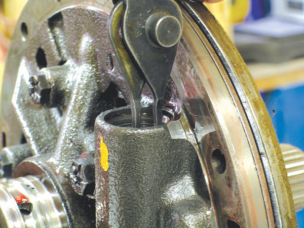
2. Open Partition

With a 1/8-inch round file, open up the partition in the picture. Do not scratch or nick the bore where the brake valve is located. Remove at least 50 percent of the partition and clean the case thoroughly to remove all the metal shavings.
3. Remove Center Seal

Remove the center seal on the direct drum. No seal is used at the location shown. Install new inner seals and outer seals on the direct drum apply piston.
4. Install Springs

Install 16 new gold-color springs on the direct drum apply piston, and install the retainer and snap ring. Set the clutch pack clearance to .050 to .080 inch.
5. Remove Band

Remove and discard the intermediate band and the apply piston in the case. They are not used with a transbrake application.
6. Remove Seal

Remove both seals from the accumulator piston located inside the rear servo assembly. Some seals are metal here. Some pistons use solid Teflon seals. Carefully cut them with a pocket knife and pull them out of the grooves. No seals are installed on the piston during assembly.
7. Install Check Ball

Drive the 1/4-inch steel check ball provided into the oil passage at the bottom of the accumulator bore in the case.
8. Smooth-Out Servo Cover

Make sure that the rear servo cover is flat. Attach a piece of fine grit sandpaper to a flat surface and gently work the cover in a figure-8 motion until it is flat and smooth.
9. Replace Modulator Valve

Remove the stock modulator valve from the case and replace it with the TCI brake valve and spring.
10. Install Solenoid

Install the TCI solenoid over the new brake valve. Use the stock modulator retainer and bolt to hold it in place.
11. Remove Center Support Ring

Remove the second ring from the center support assembly. Shown here is a Teflon ring. Carefully cut the ring with a pocket knife and pull it out of the groove. Hooked iron rings may be used here as well. If so, just unhook the ends and remove the ring by spreading it out and lifting it off the center support. Remove the upper ring first; then put it back in place.
12. Remove Snap Ring
Gently clamp the oil pump in a soft-jawed vise or between two blocks of wood. With a pair of snap ring pliers, remove the snap ring over the PR valve assembly. It may help to push down on the assembly with a flat-tip screwdriver while removing the snap ring.
13. Replace Pressure Regulating Valve Assembly

Remove the pressure regulating valve assembly from the oil pump. Replace the stock pressure regulating spring with the one from the TCI TransBrake kit. The assembly may include horseshoe shims below the spring retainer.
14. Use Supplied Gaskets

The TCI-supplied valve body gaskets must be used with the TransBrake. They are clearly marked “Case” and “VB,” and must be installed in the correct locations.
15. Install Separator Plate

The separator plate from the TransBrake kit must also be used. No additional drilling or other modifications to it are required.
Written by Cliff Ruggles and posted with permission of CarTech Books

If you liked this article, you will LOVE the full book!
Get your copy here.