Muscle Car Handling Upgrades: Rear Suspension System
Since the focus here is on muscle cars, I only address rear suspension systems that use a solid-type rear axle. Even so, there are a lot of different types of systems. Unlike front suspensions, which basically fall into either SLA or MacPherson strut configurations (at least for our purposes), rear suspensions vary wildly in configuration and function. The first question that probably comes to mind is, “Which one is best?” Well, the simple answer may sound like a bit of a cop out, but there is no best type of rear suspension design. They each have their good and bad points.
More than likely, whatever suspension is in your car from the factory is usually the one you should stick with. That’s okay, though, because proper setup and parts selection make more difference than what basic format you run.
Let’s start with the most common factory rear-suspension formats, and then move on to the more exotic factory and aftermarket racing types.
I’ve included some developmental background on many of these systems to add some historical perspective. Why? I want you to realize that when a company comes out with some all-new, trick-of-the-week suspension part, it’s almost certainly been done before, many times, and probably prior to World War I.
Every solid-axle rear suspension needs to perform several different functions. Its primary job is to locate the axle assembly under the car. This includes lateral location, fore/aft location, controlling pinion angle under acceleration and braking, and more. Doing all of these things well, and under all conditions, is complicated! What’s more, the rear suspension also dictates the rear roll center, anti-squat percentage, instant center, and side-view-swing-arm (SVSA) length, which all have a pronounced effect on how the car drives.
Rear Suspension
Some muscle cars use parallel leaf springs, such as early Mustangs and Camaros. Others use a triangulated four-link design with coil springs, like the GM A-body and Fox-body Mustangs, or a three-link with a Panhard bar like many 1960s B-body GMs and full-size Fords. Still others use a torque-arm arrangement like the 1982 to 2002 Camaros and Firebirds. The one thing that all of them share is a solid or beam-type rear axle assembly. Very few cars from the muscle car era used independent rear suspension, most notably the Corvette, but since they’re really sports cars and not muscle cars (admittedly, the 427 and 454 ’Vettes blur the distinction) I’m not going to spend time on them here. Let’s start with some basic definitions to lay the groundwork.
Parallel-Leaf
Also known as Hotchkis-type suspension (no relation to the company), this format is very simple in concept, just two leaf springs that are roughly parallel to the longitudinal centerline of the car. That’s it. These two springs must laterally locate the axle, control pinion angle, and hold up the weight of the car. The geometry and kinematics are actually considerably more complicated than a link-type suspension.
Triangulated Four-Link
Also known as converging four-link. In this type of suspension two long lower arms are roughly parallel in plan view with much shorter upper arms converging at acute angles, generally 38 to 43 degrees to the centerline of the car, in order to triangulate the suspension and laterally locate the rear axle. As a result, these suspensions use no separate lateral axle locator. This format is rife with performance compromises and opportunities for dynamic binding, but is very compact and yields a roomy trunk and backseat. It’s a good reminder of where the original designers’ priorities lay. Factory triangulated four-link suspensions are characterized by extremely high roll centers and often very erratic handling.
This suspension doesn’t do anything particularly well, but with the right components and tweaking it can be made to work surprisingly well. Aftermarket triangulated four-link suspensions that were designed with performance in mind can avoid most of the pitfalls of the factory designs, and often perform extremely well.
Parallel Four-Link
These suspensions use four links or arms that are all parallel as viewed from above. These links control axle rotation and fore/aft axle location, but require a separate locating device such as a Panhard bar (sometimes referred to as a fifth link), a diagonal (in plan view) track locator, or (less often) a watts link to control lateral axle location. The best examples from the muscle car era were used on the big-block GM B-body cars of the early to mid 1960s. Aftermarket suspension clips with a huge range of adjustment for instant center and anti-squat adjustment are offered by many companies for hardcore drag racing using this format. These typically use a diagonal track bar, wish bone, or short Panhard bar for lateral axle location. Being optimized for straight-line use they’re generally a poor choice for performance handling applications but can be modified to work in those applications if, for example, you wanted to convert a 1980s Pro-Street car into a modern Pro-Touring car.
Three-Link
Three-link suspensions use two parallel (or close to parallel) lower arms and a single upper arm. This upper arm can either be centered or offset to the right side to counter axle torque. A lateral-axle locator consisting of a Panhard bar or watts link is a necessity because the single upper link is unable to adequately locate the axle laterally. This suspension can strike a very good balance between geometry, freedom of movement, and adjustability. It’s able to run much higher anti-squat numbers than a parallel four-link without inducing kinematic binding. The single upper link and its mounts must be very, very stout. This suspension is quite common in solid-axle road race and short-track circle-track cars. The only American production cars currently running a three-link suspension (with Panhard bar) are the SN95 Mustangs.
Ah, the factory GM triangulated four-link in all its glory. The lower trailing arms locate the rear axle in yaw and transfer forward thrust from the tires to the chassis. The converging upper links provide almost all of the lateral axle location and control pinion angle under acceleration and braking. This was designed to be a soft-riding suspension that was compact in order to provide a roomy trunk and backseat. The designers succeeded admirably in attaining those goals. Performance cornering was apparently not a design criterion.(Photo Courtesy Tad Banzuelo)

Torque Arm
These systems use a pair of parallel lower arms and a lateral axle locator much like a parallel four-link but rather than having one or two upper links they use a very long single arm that’s rigidly mounted to the axle. This arm runs along the centerline of the car or just slightly off center for better packaging. This system has a number of built-in limitations, including very limited anti-squat and a low instant center with a fixed-side-view swing-arm length (SVSA). It’s a capable suspension for handling purposes and has been used successfully for drag racing when the rest of the car is tuned to work around its limitations. The most prevalent example of this suspension is found on GM F-body cars (Camaro/Firebird) from 1982 to 2002. It was also used on GM H-body cars (Vega, Monza, etc.) starting with the Vega in 1976.
Ladder Bar
Ladder-bar systems use two parallel arms that are rigidly mounted to the axle tubes (no pivots) with Heim ends or bushings mounted to the frame at the forward end. This effectively hinges the whole axle in a horizontal plane. Usually a short Panhard bar or diagonal track locator is used for lateral axle location.
This suspension is very popular in drag racing but sees little use anywhere else. Because the rear suspension allows for essentially no body roll at all, drag cars tend to launch nice and flat. However, when cornering it binds up and causes the car to be very skittish, much like going around a corner too fast with a shopping cart. Ladder-bar suspension has no place on a performance-handling vehicle.
Pickup Points
I’ve covered these in Chapter 1 and they’re just as important in determining the geometry of the rear suspension as they were up front. These are the pivoting points of the suspension.
This tech tip is from the full book, HOW TO MAKE YOUR MUSCLE CAR HANDLE - REVISED EDITION.
For a comprehensive guide on this entire subject you can visit this link: LEARN MORE ABOUT THIS BOOK HERE
SHARE THIS ARTICLE: Please feel free to share this post on Facebook Groups or Forums/Blogs you read. You can copy and paste this website link: https://www.cartechbooks.com/blogs/techtips/muscle-car-handling-upgrades-rear-suspension-system
Binding
This is simply resistance to movement. Binding issues turn up very frequently in rear suspension design because you’re often asking bushings to be compliant in more than one direction at once. That is to say they can’t simply pivot, they need to pivot and twist at the same time. Depending on the hardness or durometer of the bushings and the rigidity of the other suspension components, this can lead to effectively altering the dynamic wheel rates of the rear suspension. This effect is often non linear. That’s a good recipe for quirky handling so you generally want to avoid unnecessary binding in any suspension system.
Instant Center
The rear instant center is determined much like the front one with the exception that you need to look at the suspension from the side rather than from the front of the car. On multi-link-equipped cars, simply draw lines through the pickup points of each bushing as seen from the side; your instant center is where those lines converge.
The rear suspension pickup points are highlighted with crosshairs. The front lower pickup points are hard to see and are partially blocked by the crossmember. The points in plane view (as shown and side view) dictate the rear suspension’s geometry.

As the suspension moves, the trailing arms swing in arcs. This moves the ends of the axle assembly forward and aft, in effect steering it in plane view. Ideally, the axle moves the same amount, in the same direction on both ends when the car rolls, which produces virtually zero roll steer. Roll steer can be used to tune handling characteristics but can be very tricky to work with in that way. (Photo Courtesy Chris Alston’s Chassisworks)

Anti-squat
You often hear drag racers using this term because it has such a profound effect on straight-line traction. It’s expressed as a percentage. Lower percentage numbers tend to provide poor straight-line traction but keep the rear wheels planted well during heavy braking. Very high percentages yield much better straight-line traction, but can unload the rear tires during hard braking making them lock up and sometimes spinning the car. Like most things, there’s no free lunch. The trick is to find the best balance for the car and type of driving or racing you’re doing. That’s why anti-squat is often made adjustable. I discuss more about how that’s done in Chapters 8, 9, and 10.
Roll Steer
Roll steer occurs when the rear axle is no longer perpendicular to the center-line of the car. In virtually any solid-axle suspension you can imagine, the components each swing in some kind of arc. This moves the ends of the axles front and back slightly as the suspension moves up and down. That causes the rear axle to have its own steering inputs. As you might imagine that’s generally undesirable. Longer leaf springs or links create milder arcs of movement so they’re generally a good thing. Usually you have little or no control over that, so the only method available to reduce roll steer is to carefully check the angle of the springs or links in side view. This can be done through adjusting ride height or by moving the actual mounting points vertically. Getting them level with the ground at ride height is a good rule of thumb for minimizing roll steer.
Relationships
We’ve already seen how complex some of the relationships between various parts and settings in the front suspension can be. The rear suspension is no different. When you change anything, be it a parts change or setting change, it causes several reactions that affect the whole car. Some may influence handling, some braking, another may cause the car to feel quirky to drive. That’s why you have to consider carefully how the rear suspension interacts with the front. After all they’re opposite ends of the same car. It’s quite possible to have a very good front suspension and a very good rear suspension that work very poorly together.
This is a common place for hot rodders and sometimes even race car builders to miss their mark. In pursuit of better performance in one aspect, on one end of the car, they sometimes cause a conflict with the other end. The difference is that when this happens to the race-car guys, they know it, and the street-car guys often don’t. In a competitive environment if your car isn’t set up just so… you lose. If it’s bad, you lose bad. Hmm, time for a few changes then. With a street car the builder is often unaware that he’s left quite a lot of performance and/or drivability on the table, because he doesn’t have a really good yardstick to measure the car’s performance.
That’s just one of many good reasons to try a little friendly competition. Local autocross events usually allow anyone to run as long as their car is safe. You’ll have a blast and you’ll learn a lot about both your car and your driving. You’ll probably get lots of tips from the other participants too. Some tips will be good ones. Many folks find that the biggest detriment to good performance is the loose nut behind the wheel. Yeah, that means the driver. Lots of practice takes care of that issue though, and practice is fun! What’s more, competing lets you know if you’ve got a pretty good set up or if it needs help. (I dig into this further in the tuning section.)
In the meantime, if you don’t have the time or inclination to research every component and setting change yourself, make sure you hook up with a suspension provider that can answer all your questions, set you up with a proven package for your car, and provide tuning support after the sale to get it dialed in. This book gives you some valuable tools to help you judge if a suspension provider is really on the ball or if they’re selling snake oil.
So how can you tell if the rear suspension is a good match to the front suspension? If, for example, you’ve got the front end set up with proper geometry, springs, shocks, etc., for performance handling and you’re installing a drag race ladder bar setup in the rear, then be prepared for some disappointment. Like-wise a drag car with ladder-bar rear suspension would get lackluster ETs and 60-foot times out of that same performance-handling front suspension package, and it will still corner like a cow on a barstool.
In other words, parts and setups idealized only for one specific type of competition and its particular rule set will likely compromise the all-around performance potential of your muscle car.
Both ends of the car should agree on what it is they want to be good at.
I get calls and e-mails every day from folks who say they don’t want much out of their cars. They’re not going to race it; just drive it on the street. If they can just make their 1965 GTO or 1969 Mustang or whatever, handle as good as a new Corvette and still run 10s at the drags they’ll be pretty happy with that. Umm, yeah, I guess so! Just realize that turning a vintage iron “pig’s ear” into a modern performance “silk purse” is a complex task and won’t happen by accident or by throwing a random bunch of cool-looking parts at the car. You need to have all of your ducks in a row to get it right.
You’d be better off making a few small compromises at each end of the car, building in plenty of adjustability, and blending together the various features to make one well-balanced, versatile package. Since we’re not bound by a sanctioning body’s rules, why not build a muscle car that combines classic style and good looks with the knockout punch of a heavyweight boxer and the nimble flexibility of a black-belt martial artist? This combination has both serious power and handling. While it has more size and mass to deal with than our fictitious welterweight boxer, the advanced martial arts training, representing a very well-balanced suspension package and good adaptable tuning, make very good use of it and make it more agile and flexible than most would ever suspect. This balance between power, agility, and adaptability would make our muscle car analogue one bad hombre under almost any conditions, anywhere, and at any time.
I hope by this time it’s clear that you can’t use single-purpose parts to get this done, so let’s examine some configurations, what works, what won’t, and why.
Drag racing, as I’ve said, is a particularly specialized motorsport. Many of the mods that work well for drag racing make a car much worse for any other type of driving. Tall, soft, drag springs and 90/10 shocks make any front end handle very poorly. Traction aids can bind up the rear suspension, lack of front sway bars can cause excessive body roll, and huge rear “drag bars” can cause massive oversteer. Aggressive four-link anti-squat and instant center settings can cause the suspension to bind in articulation and/or cause undue roll steer. Tiny “pizza cutter” front tires yield a small improvement in ET on the strip but make any kind of cornering almost a pointless stunt.
To a lesser extent, handling mods can also reduce drag-strip performance. While drag-race-specific parts can make a car’s street performance terrible, sometimes even dangerously bad. Handling mods only reduce off-the-line traction at the strip. The cars usually MPH very well. Stiff springs and firm front shock rates reduce weight transfer and conspire to reduce initial traction. Fundamentally good front-end geometry is always good, and bad is always bad, so feel free to do well-thought-out geometry mods on the front end. Some of them, like correcting bump steer, make the car easier to drive at the drags too.
If your rear suspension is adjustable keep the anti-squat numbers sane, the lower arms parallel with the ground, and the car can hook reasonably well, but still corner and stop without unloading the rear suspension and locking up the rear tires. If it’s adjustable you have the option to dial it in for the drags and change it back again later. If your link suspension is not adjustable, be wary of mods that change it for a single purpose such as “no hop bars,” which also drastically change the rear roll center height for the worse and degrade handling.
If you have leaf springs, resist the urge to get purpose-built drag-racing springs. Instead, go with some good all-around performance spring packs. If you use traction aids such as traction bars, make sure you can deactivate them easily by removing the links or the snubbers on each side. That takes them out of the equation when you’re corner carving and prevents them from binding up the springs and causing quirky handling issues.
Adjustable shocks are great to have on any performance car and truly a God-send on a multi-purpose car. They are a huge help under any conditions. When taking a street car that handles to the drags, the double-adjustable variety is especially helpful because you can alter the jounce versus rebound ratios to effectively make them into drag race shocks and get some much needed weight transfer. (I cover this in depth in Chapter 4.)
Spring rates require some compromise but it’s still possible to get good handling and a decent launch with a set of what I like to refer to as “performance touring springs.” Manufactured by many companies, these are firmer than stock but much softer than a dedicated set of road race springs. They yield handling nearly as good as road race springs, but with a surprisingly good street ride. Here again the front and rear need to match; you can’t run trick drag springs in the front and performance handling springs in the rear. I discuss springs and tuning in Chapters 8, 9, and 10, but for now remember that the car is one large system, not two ends, and you need to get all the parts and settings to work in sync.
Leaf-Spring/Hotchkiss Suspensions
This is certainly the most basic of the designs I discuss and a very common one, having been used by every domestic manufacturer at one time or another. I defined it earlier as simply two leaf springs mounted roughly parallel to the longitudinal centerline of the car. It’s often referred to as Hotchkiss-type or Hotchkiss drive after its inventor, Benjamin Berkeley Hotchkiss (1826 to 1885), who was the American-born owner of the French Hotchkiss Company. This company produced automobiles for many years, but was best known for its military vehicles. The leaf-spring format was only part of a package that included a driveshaft with U-joints and the sliding splined-front-yoke design we’re all used to today. Most other cars at that time used a torque tube or an open chain drive. That gives you some idea of how old this system is.
There’s a lot more to a parallel-leaf-spring suspension than meets the eye, though. Because only two main components are being called upon to perform numerous different functions, this suspension’s kinematics are actually very complex.
These leaf springs are almost completely parallel. Some cars have them splayed outward slightly at the rear, which can cause wheel and tire clearance issues with really large rolling stock. (Photo Courtesy Ray Campbell)

This simple stack of flat strips of steel is expected to do many different tasks at the same time. (Photo Courtesy Ray Campbell)

Good old leaf springs. They look so simple but, when you delve into their kinematics, they are amazingly complex. (Photo Courtesy Total Control Products)

The simple stacks of flattened spring steel are expected to longitudinally and laterally locate the axle, control pinion angle, and not distort under either acceleration or heavy braking. They locate the instant center, define the roll steer characteristics, anti-squat, and roll center, and of course, hold the weight of the car at its desired ride height, all at the same time. That’s a tall order for such a simple system and it’s no surprise that there are a lot of compromises involved. Production simplicity and original-equipment (OE) packaging considerations only add to these issues.
Factory leaf-spring systems tend to favor ride quality and production cost over performance. That means the spring packs are generally thin and flexible, which allows spring wrap-up under hard acceleration and heavy braking. They’re almost always mounted in soft rubber bushings (antique cars usually had greaseable steel bushings) and supported at the rear with thin shackles that have poor resistance to lateral deflection. While these suspensions function acceptably on a typical commuter car, they leave a lot to be desired in performance applications.
Improvements to this type of system are generally made by one of three methods: refinement, augmentation, or replacement.
Refinement
Refinement can be either the simplest or the most complicated and time-consuming method. It generally starts with replacing the factory soft bushings with many materials and shapes including polyurethane, spherical bearings, Delrin, solid aluminum, or even bronze. It’s important to keep the properties of the replacement bushings in mind as you work out the details of the system. Poly bushings can have non-linear binding issues due to their inherently high degree of static friction. They can also have a tendency to squeak. Both issues can be adapt-ability with perfect lubrication, but that’s usually easier said than done.
Delrin (DuPont’s trade name for its hard acetyl plastic) or solid metallic bushings pivot freely on one axis, but don’t allow for deflection in torsion, causing the leaf spring to take more torsional load. This generally induces more overall spring rate in proportion to the number of degrees the spring is deflected. Make sure you want that additional rate before you install them. Some use this as a mild type of faux sway bar.
Spherical joints do the opposite. They reduce torsional load on the leaf springs and reduce the effective roll rate. Note that spherical joints also allow the springs to pivot from side to side in plane view, which increases the side loading on the rear shackles and bushings. Extra-beefy and/or cross-braced shackles and solid upper shackle bushings may be necessary to achieve predictable handling. A separate lateral axle locator may also be required, which I discuss in “Augmentation” below.
Solid and spherical metallic bushings increase some transfer of noise, vibration, and harshness (NVH) to the chassis and passengers, often in the form of buzzing or tactile vibration.
You can also use a combination of these options, such as a solid bushing at the top of the rear shackle to help reduce lateral deflection, or a spherical joint at the front of the spring to reduce binding and radial deflection, or a rubber or poly bushing set at the bottom of the shackle to absorb some NVH. Some combinations work better for drag racing and others for cornering. Testing and tuning is the only way to really know what works best on your specific car.
Delrin bushings are among the top choices for performance applications. Changes in a leaf-spring bushing’s composition alter the spring’s torsional resistance. Low-compliance bushings and beefy shackles (like these DSE units) make the spring react faster. Softer bushings deflect before the spring begins to twist, which delays the reaction. The latter likely requires more roll rate from sway bars, etc., assuming all else is equal. (Photo Courtesy Detroit Speed and Engineering)

Notice two interesting features. One is the spring clamps, which are a common component keeping all of the spring leaves working together, even in droop. If removed, only the main leaf would contribute rate in droop, and that side of the car would lift very easily when on the inside of a turn. Look closer to see another feature: a synthetic anti-friction pad between the ends of the spring leaves. This allows the spring leaves to slide against each other smoothly, contribute a consistent rate, and improve ride quality. (Photo Courtesy Detroit Speed and Engineering)

Here’s another variation on the same theme. The custom spring packs on Ray Campbell’s off-road race Jeep use full-length strips of polypropylene. Full-length strips were used due to the dirt and rust issues that can cause off-road leaf springs to seize up. Note the lack of spring clamps on the rear half of the springs, which allows the leaves to separate during a hard launch, lifting the body and pushing the tires into the track. (Photo Courtesy Ray Campbell)

A centrally mounted torque arm can be a good way to improve straight-line traction and braking stability without compromising handling. It’s important to have a shackle or similar front mount, because the torque arm and leaf springs swing in different arcs. Without the shackle they would bind against each other. Note the spherical bearings in the shackle to prevent torsional binding. This TCP unit is intended for Mustangs, but could easily be adapted to other cars. (Photo Courtesy Total Control Products)

A dramatic depiction of why slapper bars are a bad idea for handling applications. The suspension (on the outboard side) is locked up by the bars in bump, causing the inside to lift. At rest, this car tucks the rear tires! Later on you’ll see how this same car corners without the slapper bars and with an SC&C StreetComp front-end-geometry overhaul.

Spring wrap occurs when rotational axle forces bend the spring into a serpentine shape. This not only adversely affects pinion angle, but tends to unload the tires, setting up a cyclic action we know as “wheel hop.”

Even the spring clamps can have an effect on performance. It’s fairly common on drag cars to remove the spring clamps from the rear half of the springs. This allows the leaves to separate in droop. Combined with a pinion snubber, specialty drag race springs (known as Super Stock springs among Mopar fans), or other traction aids can help plant the tires. It is not recommended for performance handling because it reduces roll resistance in droop.

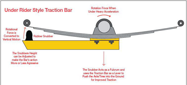
Probably the most common genre of traction bars is called “slapper bars.” Mounted rigidly to the spring pad, they act as a lever, with the rubber snubber working as a semi-compliant fulcrum. The leverage produced by the bars pushes the axle assembly and tires into the ground for improved traction. Unfortunately, they also bind in roll and, if set too aggressively, the bar on the outboard side in a turn can even become the new roll center of the rear suspension, causing the inside to lift dramatically.
Then, there are the leaf-spring packs. This is a broad subject, so I cover only the main points. The front half of the spring acts more or less as a semi-flexible suspension link, due to its fixed frame mount. This locates the axle in the car longitudinally (front to rear). It also takes the majority of the load under acceleration and braking. Adding stiffness in the form of more spring leaves, thicker spring leaves, and/or longer supporting leaves that extend to the spring eye, all tend to improve straight-line traction and reduce wheel hop.
Adding these features only to the front half of the springs does so with less increase in overall spring rate than if you added it to the whole spring pack. Adding leaves (or leaf thickness) also adds torsional stiffness and weight. The first may or may not be desirable depending on the rest of the suspension package. Adding weight is almost always undesirable.
Most factory springs have progressively shorter leaves from top to bottom, and few have a second leaf that reaches the front spring eye. This means part of the main leaf has no additional support and can contribute to wheel hop, main leaf deformation, and even failure. Heavy-duty springs often have a second leaf that’s much longer on the front half of the spring than the rear, extending all the way to (and under) the spring eye for better support. Off-road springs often go a step further and wrap the front spring eye in the second leaf. This is called a “military wrap” and provides a safety net in case the front half of the main leaf should break.
Factory springs are generally tapered at the ends. Often aftermarket springs have square-cut ends. These generally work fine, but it’s been pointed out that they do form stress points for the leaf above them. This may lead to some reduction in spring life and it would be best if the ends of the springs were cut at an angle on each side to eliminate any such concerns.
Since the leaves of the spring pack need to slide against each other as the spring compresses, friction also changes their actual rate. Years ago many antique cars used springs that were thoroughly greased throughout, and then wrapped with thin metal and clamps to hold the grease in. Today, some springs use a Teflon button at each end of the leaves or a strip of Teflon the full length of each leaf. These provide smooth, consistent spring action. It’s not absolutely necessary, but it is a nice feature.
The arch of the springs can also be changed to alter ride height. The flatter the springs are at ride height, the better they resist lateral deflection and the better they laterally locate the axle. A flat piece of steel is very difficult to bend laterally if it’s laying flat. Spring bushings, likewise, are nearly noncompliant to axial load. When you introduce an arch to the steel, you’re twisting it like a flat torsion bar. The leaf bends laterally much more easily, and the bushings (solid metallic or Delrin bushings notwith-standing) are now free to deflect radially as well. It becomes quite easy to twist the springs, and the axle can move more easily from side to side.
Less spring arch also decreases roll steer. However, if the leaf-spring packs are too flat at static ride height, they tend to go into a negative arch in compression. A negative arch moves the angle of the shackles in the opposite direction and imparts an undesirable quirky feel to the suspension. Like everything else suspension related, leaf-spring arch is a delicate balance.
As I touched on above, the rear shackle also plays an important role in the dynamics of a leaf-spring suspension system. They’re often too flimsy for good lateral axle control, and replacing them with much more beefy and sometimes cross-braced or boxed versions generally yields a more precise-handling car. The length of the shackle can be changed to alter anti-squat or fine tune ride height (although there are better ways to do it). Use caution and common sense to prevent the shackle from getting too long (which allows more deflection) or too short (which can cause it to bind the spring up before it can achieve its full travel).
Shackle angle also has an effect on spring rate and handling, and as a general rule they should be oriented at 90 degrees to a line drawn straight through the front and rear spring eye bushings. If the shackle is tilted farther forward than 90 degrees, it slightly increases the rate of the springs. If it’s angled back-ward it softens it. You’ve seen cars with really tall shackles (sold as universal fit) used to jack the back end of a car up to clear some big tires—usually on wheels with the wrong backspacing. You know, the jacked up 1970s “stink bug” look. Avoid that.
Even the spring clips (or bands) have an effect on spring performance. If you run them, check the factory rubber-lined clips to make sure the rubber is still intact and that the clips haven’t slipped out of position. Loose clips yield inconsistent spring rates, especially in rebound. They have little effect during spring compression because the springs are stacked one on top of the other with the main leaf on top, pressing down on all of them. In rebound, the clips (or bands) are the only things holding the main leaf to the ends of the springs making up the rest of the pack. When clamps move around, it may cause one or more leaves to be left out of the pack’s total rate in rebound. Without any clamps, the main leaf deflects by itself and the remainder of the pack just sits at rest, contributing nothing.
This can also be used to tune the spring packs. In drag racing, for example, it’s common to use bolt-together clamps on the front half of the spring, which not only hold all of the leaves together, but also clamp the leaves so tightly they can’t slide against each other. This increases the spring’s rate and makes the front half of the spring into an impromptu ladder bar. The back half of the springs are left with no clamps, which allows the leaves to separate freely, allowing the rear of the car to lift up and press the rear tires down harder on the track. At least that’s the theory, which tends to work better on some cars than it does on others.
As you can see, there’s a lot to consider when it comes to refining a leaf-spring rear suspension. Some of the parameters are fairly easy to change, such as bushings or shackles, while others (like changing the format or arch of the leaf packs themselves) are more difficult (I discuss changing leaf-spring rates later). Because tuning leaf-spring systems can be a bit daunting, it’s very popular (and often quite effective) to either leave the springs alone or just install aftermarket spring packs and further tune the suspension.
Augmentation
By far the most common form of leaf-spring augmentation are traction bars. They come in many shapes and sizes, and range in effectiveness from very effective to totally worthless. They’re generally used to improve straight-line traction from a dead stop, as in drag racing. Most have a negative effect on handling. Some styles kill the handling altogether. Let’s take a look at the most-common types.
Slapper Bars: I’m sure you’ve seen the old standby rectangular tubing traction bars with a rubber bumper or “snubber” at the front end. They are often called slapper bars; and that’s exactly what they do. When the rear axle tries to wrap up the front of the leaf spring under heavy acceleration, the traction bar’s snubber slaps against the bottom of the main leaf near or on (preferably) the front spring eye. This takes much of the load off the springs and turns some of the rotational force into downward force to plant the tires.
When and how hard the bars engage is adjustable through altering the height of the snubber, and on many bars through adjusting the angle of the bars with J-bolts or shims. In normal driving, they’re generally just along for the ride. But in hard cornering, the snubbers can contact the springs and essentially cause an instant spike in spring rate. Since excessive rear spring rate is a recipe for oversteer, this can cause erratic handling and even sudden snap oversteer. And then you’re saying, “Hey, everything was fine a second ago, why am I going off the road backward?”
That extra stiffness occurs in compression only. So in a turn, as the outside spring gets really stiff when the traction bar binds it up, the spring on the other side is still at its normal rate and allows the body of the car to continue to roll. That can lift the inboard side of the car and result in excessive body roll. The softer the car is set up (with regard to spring rates, sway bars, etc.), the more pronounced this phenomenon tends to be. If you plan to do any serious cornering with this type of traction bar, render them basically inert by removing the snubbers and be sure the bars won’t contact the springs.
One of the oldest types of traction bar is the “under rider” style. Still common on Restomod-style Mustangs, these mount the front pivot to a solid mount on the chassis and the rear to the leaf-spring plate. Because they pivot on both ends, they don’t have any vertical leverage. Rather, they are in compression, pushing on the chassis and pulling straight back on the front half of the leaf spring. In effect, they turn the front half of the leaf spring into the top link of an impromptu four-link suspension. Because the spring is in tension, it tends not to wrap up. Usually, the pickup points are not properly aligned to avoid binding in roll or in bump (and droop, for that matter), causing binding. The front mounts are usually flimsy, single-shear affairs, and, if the car has been run hard, they are usually twisted and bent.

The cantilever-type bar is a more sophisticated link-type traction bar. The link pivots on both ends, but this time the front mount pivots on the front spring bolt and has a cross pin that bears down on the top of the front half of the leaf spring to counter wrap-up. The geometry of these bars is much better than the under riders and they can be very effective. As long as the bushings in the link don’t bind in torsion, they have little effect on handling. If you have to run traction bars on a handling application, this type is probably your best bet.

With custom leaf-spring packs featuring Super-Stock–like forward leaf bias, no clamps on the back half of the springs, and years of tweaking pinion angle, spring rates, shock dampening, tire pressure, and more, this aluminum-bodied EC4WDA race Jeep hooks so hard it can come off the transmission brake at 4,500 rpm, even on loose dirt, with hardly any wheel spin. (Photo Courtesy Ray and Brian Campbell)

Traction Bars: Traction bars that use links that pivot on each end, rather than being solidly mounted on the axle end, have a better chance for success in the twisties. This type has been used by the original-equipment manufacturers (OEMs) at times, such as on the 1967 Z28, by Shelby on the GT-350, and on Sunbeam Tigers (Max’s red 1965 Tiger on Get Smart). This design basically tries to turn the leaf springs into the top link of an improvised four-link suspension, with the traction bar forming the lower link. That takes some of the vertical force off the leaf springs, puts the traction bars in compression, and then puts the front half of the leaf springs in tension under hard acceleration. With proper geometry, they have little influence on handling but in general they’re better at reducing wheel hop than they are in adding actual traction.
More complex traction bars are also available with a bellcrank unit at the front spring eye, which induces down-ward force on the main leaf. They provide wheel-hop reduction and good traction. These are more adjustable and may or may not work in a handling application, depending on how they’re set. As a general rule, bolt-on traction bars are more likely to be part of a handling problem than a handling solution. Given that, with the proper basic configuration and due diligence to tuning them as a part of the whole suspension system, they can be used to good effect on an all-around performance car.
Add-On Ladder Bars: These should never be used with leaf springs. In addition to the issues I discuss later in this chapter, they work in conflict with the leaf springs unless spring floaters are used. If you’re going to that much effort you may as well lose the leaf springs altogether and start over with a whole new suspension system.
This tech tip is from the full book, HOW TO MAKE YOUR MUSCLE CAR HANDLE - REVISED EDITION.
For a comprehensive guide on this entire subject you can visit this link: LEARN MORE ABOUT THIS BOOK HERE
SHARE THIS ARTICLE: Please feel free to share this post on Facebook Groups or Forums/Blogs you read. You can copy and paste this website link: https://www.cartechbooks.com/blogs/techtips/muscle-car-handling-upgrades-rear-suspension-system
It is possible to add a device designed specifically to help in hard cornering, which enhances rear-axle lateral locating and RC defining. These components are intended to reduce unwanted lateral axle movement to produce a consistent and linear rear suspension that’s easy to drive hard. The two major types are Panhard bars and Watts links. In a leaf-spring suspension, they have some distinct advantages and disadvantages.
The Panhard bar is the easiest to fabricate and install. You should try to set its height near the natural RC of the leaf springs, make it as long as humanly possible, and keep it level with the ground at ride height for best performance. The Pan-hard bar works best on suspensions with limited vertical travel. This is because its axle-mounted end travels in an arc that laterally displaces the rear axle, which induces binding with the leaf springs, and can cause erratic suspension behavior. Remember that some bushing configurations help to minimize this issue, while others aggravate it. This is yet another reason to think before you build.
Watts links are more difficult than Panhard bars to fabricate and install, but some application-specific ones are avail-able as direct bolt-in packages, which greatly simplifies things. A properly implemented Watts link keeps the rear axle almost perfectly centered under the car, which is okay for the leaf springs because that’s where they are intended to keep the axle anyway. The same caution applies to keeping the RC near its original location to prevent unnecessary conflict. But it doesn’t have to be exactly the same: You have some latitude to adjust the car’s behavior—just keep it in the same general neighborhood.
An axle-mounted Watts keeps the RC closest to the original RC throughout the rear end’s travel, but a frame-mounted Watts keeps the RC the same distance at all times from the CG, maintaining a consistent length on that rear moment arm. Experts argue about which is best, but both can work extremely well. The frame-mounted Watts link’s crossmember adds chassis stiffness, and it is easier to make as a bolt-on, fully adjustable package. This makes them especially attractive. I get more in depth with the Panhard and Watts designs in Chapter 3. But as they pertain to leaf-spring suspensions, the Watts link is generally the superior of the two.
Replacement
In its simplest form, I replace the original leaf springs with aftermarket performance leafs or possibly composite leafs. Both are used to increase the rate of the springs and the latter can yield a reduction in weight as well. But the conclusion here is that the Hotchkiss-drive leaf-spring system just needs to go, making way for a more modern system altogether.
The most common replacement systems are of the four-link variety, although there are three-link and torque arm systems available as well. The following suspension systems apply to those installed as a conversion as well as to cars that were originally equipped with them. (I address the details of each system in Chapters 8, 9, and 10 pertaining to specific vehicles.)
Four-Link Suspensions
Four-link suspensions are some of the most commonly used by OEMs in the muscle-car era. If they didn’t use leaf springs it’s likely the car had a four-link of some kind, almost always a triangulated four-link (sometimes referred to as a con-verging four-link). This system is a manufacturer’s dream. Four links (or arms), usually made from simple (cheap) sheet-metal U-shaped channel with rubber bushings, a pair of coil springs, and some shocks—and it’s done. It’s compact too, yielding lots of backseat and trunk room. The cars drive okay and have pretty good ride quality. An OEM’s work was well done at this point (at least back then).
Well, sort of. Some of us want more out of our cars than the average owner, especially considering what the average driver was accustomed to back then. I suspect the engineers who designed these cars would think we’re all nuts for pushing the overall performance envelope as far as we do these days. Performance handling wasn’t a top priority when these cars were originally designed; it’s no wonder these factory suspensions come up way short today. If these four-link suspensions were people, they’d be sporting plaid slacks and Henry Kissinger glasses.
The essence of the triangulated four-link is that at least two of the arms are angled in plane view, typically 30 to 45 degrees on each side to the centerline of the car. On the cars I’m discussing here, the upper links are the ones with the very acute angles. This allows them to multi-task and laterally locate the axle, establish the rear roll center, and also do the usual job of maintaining pinion angle under acceleration and braking.
Triangulated four-link suspensions are popular due to their simplicity. Four links control all of the rear axle’s movements; this Chassisworks rear clip is a good example. It has performance geometry, rigid billet-aluminum arms, greaseable Delrin race pivot-ball flex joints, and a frame-mounted sway bar. These features put it a cut above similarly-formatted factory suspensions. (Photo Courtesy Chris Alston’s Chassisworks)

Unfortunately, when you try to do too many things at once, you don’t do any of them well. That’s certainly true here. When you look at the design features used to build a set of rear arms for these cars, conflicting requirements are immediately apparent. For example, in order to do a reasonable job of laterally locating the axle assembly, you need very rigid arms fitted with pivots that allow little or no deflection. If the pivots are soft rubber, they deflect and allow the axle to move about and degrade handling, so rock-hard bushings would seem to be the order of the day. But, that would be ignoring some of the other kinematics present in the system.
When the axle moves vertically, you notice binding in the angled upper arms. This is because the upper arm’s frame side pivots are far off the centerline of the vehicle, but the axle side ends are very close together, causing them to swing in conflicting arcs. At any height except the car’s original ride height, the arms begin to pull against each other and against the mounts on the axle. To reduce this binding, you need very compliant (soft) bushings to allow the arms to essentially change in length a fraction of an inch. If you don’t do this, you have greatly reduced ride quality and some degree of undesirable suspension binding. Also consider how, when the car’s body rolls and the axle needs to articulate, that the arms need to be free to move in torsion. In other words, they need to be free to twist or, once again, you incur suspension binding and erratic handling issues.
So, how can you design a set of arms to allow complete freedom from binding throughout the rear axle’s total range of movement, and still keep the axle perfectly centered under the car? Simply put, with this system, you can’t. That brings me to the word of the day, “Com-promise.” You’re not going to make this system kinematically correct, but you can make it function pretty well within its actual range of motion. The suspension may allow the axle to articulate 20 degrees, but have you ever seen a car exhibit 20 degrees of body roll? About 6 degrees is a lot, and 10 degrees would feel like you were cornering on the door handles. So you really only need the suspension to work freely within the range of motion the car actually uses. That makes matters much easier.
You are still limited by the short factory upper arms and their radical arcs of travel but, by carefully weighing all the factors involved, you can put together an effective package for performance use. The system can work pretty well, but you have to pay very close attention to the details to get it right. (See Chapter 4 for more details on replacement trailing arms).
Parallel Four-Link Suspensions
This variation of the four-link rear suspension is a lot less common in factory cars. The only ones that come to mind are the early- to late-1960s Impalas. The base cars used a three-link with an offset upper arm, but the SS models added a second upper arm to make a complete four-link. Much more common are aftermarket adjustable four-link-suspension packages made for drag racing. There are also a few designed as replacements for leaf-spring suspensions in early Camaros/Firebirds.
Because the links are all parallel, they’re unable to laterally locate the axle assembly. This means you need to introduce a separate lateral axle-constraint system (such as a Panhard bar or Watts link) to the total package to provide that lateral location and also to define the rear roll center. As is always the case, the devil is in the details. The parallel four-link, properly designed, can be a great all-around performance suspension, or it can be configured to do only one thing well to the exclusion of all else.
The execution of the lateral axle locator is one of the most important factors in determining how versatile a parallel four-link suspension is. Drag race four-link suspensions typically use one of two axle locating devices: a short Panhard bar (often mounted to the top of the differential housing) or a diagonal track locator bar. As seen in plane view, this bar runs diagonally between a front lower-link mounting point and an opposite rear one, bisecting the rectangle formed by the lower links, axle, and frame mounting crossmember and turning it into two non-compressible triangles. It’s elegantly simple and lightweight, but it’s poorly suited to performance handling.
This tech tip is from the full book, HOW TO MAKE YOUR MUSCLE CAR HANDLE - REVISED EDITION.
For a comprehensive guide on this entire subject you can visit this link: LEARN MORE ABOUT THIS BOOK HERE
SHARE THIS ARTICLE: Please feel free to share this post on Facebook Groups or Forums/Blogs you read. You can copy and paste this website link: https://www.cartechbooks.com/blogs/techtips/muscle-car-handling-upgrades-rear-suspension-system
The nature of this method of triangulation inhibits axle articulation, by dynamically putting the track locator in compression. This is a good thing for a drag car because it more evenly loads the tires and makes for a flatter launch. It’s bad for cornering performance because, like any type of suspension binding, it can cause stiff and erratic handling. It also yields a very low rear roll center. Other methods, such as X-braces (which are basically two track locator bars, crossed and joined in the center) and wishbones, are sometimes used with parallel four-link suspension, but neither of these is any better suited to handling use.
Many muscle cars came with triangulated four-link suspension designs. With the proper parts they can provide surprisingly good performance and look good too. (Photo Courtesy J. Kimber)

Parallel four-link suspensions require some kind of additional lateral axle locator. This package uses a diagonal track bar. Note the lack of vertical adjustment for the arms, which means there is no anti-squat or IC location adjustment in this system. The nearly parallel links should provide good roll steer characteristics. (Photo Courtesy Chris Alston’s Chassisworks)

This view of a DSE Quadralink is a great example of a parallel four-link. All four-links swivel to prevent torsional binding, which (combined with excellent roll steer characteristics) yields a very linear and predictable rear suspension. The Panhard bar is as long as possible and is adjustable to keep it parallel with the ground at the car’s final ride height. (Photo Courtesy Detroit Speed and Engineering)

Installing the longest-possible Pan-hard bar, mounted at a reasonable height, is the most common solution to building a parallel four-link that can corner well. A good example of a parallel four-link with a long Panhard bar, idealized for handling, is Detroit Speed’s Quadralink rear suspension package for early GM F-bodies (Camaro/Firebird). Note that this is a clean-sheet design, not an adapted drag race suspension.
A much less common but potentially superior method of improving lateral location on a drag race parallel four-link is to use a Watts linkage. Because prefabricated, frame-mounted Watts-link pack-ages are available (from Fays2 Suspension), this configuration has become an increasingly popular choice.
The next big factor in configuring a parallel four-link for handling is the geometry of the links. In factory cars like the Impalas, this is fixed at a moderate, all-around setting, which serves most folks well enough as is. Drag race four-links usually have a dizzying array of mounting holes available for mounting each link. Which holes you use has a huge impact on the behavior of the suspension. Very high anti-squat settings, achieved with steeply angled arms, incur a penalty in binding during articulation. It is a familiar phenomenon: what enhances straight-line traction usually inhibits good handling.
However, a parallel four-link that is designed for optimum handling usually has its arms parallel, or very nearly so in side view as well as in plane view. The lower arms are almost always parallel to the ground as well. This format greatly reduces binding and also minimizes roll steer, making it a very predictable and linear suspension. So why doesn’t everyone use this format? Because it also has little or no anti-squat percentage and its side-view swing arm length, terminating in the instant center, is also ultra long, so straight-line traction really suffers.
Here is where our old friend compromise comes into the picture. The major advantage of a very adjustable suspension system is the option to start out with it set at a reasonable baseline, and then tune it to your liking. Typically, you’d start with the lower arms parallel with the ground for best roll steer characteristics, and then dial in some anti-squat by angling the upper arms down toward the frame side of the arms. You might start with the front of the upper arms 1 inch lower than the rear and work from there. As you add anti-squat and shorten the SVSA, straight-line traction improves but at some point you’ll begin to notice some negative effects on handling. When you reach that point, start backing off your adjustments again until you find a happy medium. You can have your cake, and eat it too, if you pay close attention to all of the details. (See Chapter 8 for more information on the four-link setup.)
Torque Arm Suspensions
The torque arm design nearly didn’t make it into this book because it wasn’t used on any of the traditional 1960s to 1970s muscle cars. But it was used on Camaros and Firebirds from 1982 to 2002, the very-limited-production 1987 Buick GNX turbo Regals, and GM Vega/Monza clones from 1975 to 1980. Since most of these cars are 20+ years old and some are certainly muscle cars, I included torque arm suspension. There are also a few torque-arm conversion packages for leaf-spring older muscle cars that have come out recently, so this section covers those as well.
Torque arm suspension is an evolution of the older torque tube suspension system. These systems have the driveshaft and suspension combined into a single unit, which is rigidly attached at the axle end and pivoted in a single massive pivot ball at the transmission tailshaft. A long diagonal brace was usually used on each side to keep the rear axle perpendicular to the torque tube. This one large tubular unit, enclosing the driveshaft, controlled all rear suspension duties except lateral location. This task was accomplished either with transverse buggy springs (like you see in a Model A Ford) or with a Panhard bar (like that used in an early 1950s Buick). A Watts link could also be used.
The torque arm suspension removes the driveshaft from the equation and uses a typical sliding yoke driveshaft. Because the front mounting point is no longer on the exact centerline of the car (and so the mount can be made more lightly), the torque arm also makes use of two lower arms similar to what you see in a four-link suspension system. These propel the vehicle and longitudinally locate the axle in the car, leaving the torque arm to control pinion angle under acceleration and braking. The torque arm itself is usually very long and most commonly mounts to the transmission crossmember or to the side of the tailshaft of the transmission case itself.
The GNX is a notable exception to this rule. Its torque arm was quite short, looking more like a single centrally-mounted ladder bar, but this was more due to packaging constraints than anything else. The front torque needs to be free to twist to allow for axle articulation. It must also be free to move longitudinally to prevent binding with the much shorter lower arms. Due to the profound difference in the lengths of these components, they swing in much different arcs. Typically, the front mount either pivots and slides in a bushing, or it has a shackle with bushings or pivots to allow for this necessary compliance.
The SVSA length of a torque arm system is determined by the forward mounting point, which means the points are generally far from the rear axle. The IC resides directly below the front torque-arm pivot point, in line with the lower arms in side view and usually fairly low, especially on factory torque arm cars that have been lowered. Some manufacturers offer dropped mounts for the back of the lower arms. These raise the IC to improve off-the-line traction, but can also negatively impact roll steer characteristics. The anti-squat percentage is limited to about 30 percent, where four-link and three-link suspensions can achieve more than 100 percent. This suspension is generally stable and forgiving, with decent all-around performance and good roll steer characteristics. It’s not particularly well suited to drag racing due to its long, fixed SVSA length, and low IC height. But it has been used effectively in that application as well, with careful attention to the overall setup of the car. Generally, the car’s setup has to be idealized for drag racing only at that point. The torque arm system is not the best multitasker due to its general lack of adjustability. Also limiting the torque arm’s popularity is the fact that the rear axle must have torque-arm-specific mounts integrated into it to allow mounting the torque arm itself.
Three-Link Suspensions
Three-link suspensions saw very limited use in muscle cars. Even then it was used as a low-cost alternative to a four-link. That’s a real shame because, of all the suspensions discussed here, the three-link arguably has the most advantages and the fewest disadvantages. A three-link suspension functions very much like a parallel four-link, but it can run high anti-squat settings and short SVSA lengths without incurring additional binding. This is due to the use of a single upper mount.
Like any link suspension, the pivots must be free to move without binding on a three-link. A three-link with hard, non-compliant bushings (such as a Delrin) and rigid arms would still bind in articulation like any other suspension. Its biggest downside is that the single upper link and its mounts are put under extreme loads, and most factory cars don’t have any suitable structures to mount them to. The backseat and trunk floor often cause interference issues as well, which can lead to design compromises for the sake of packaging. Witness the late model SN95 Mustangs, which use a three-link design with a relatively short upper link (only about 8 inches long). Very short upper links cause rapid pinion angle change and reduce the size of the suspension’s sweet spot, thus limiting effective vertical travel.
Despite fabricating issues, a properly engineered three-link suspension (with a Panhard bar or Watts link) can be configured to do most things quite well. A small number of them have been offered as kits to be retrofitted to non-three-link cars, but they tend to require quite a bit of cutting and structural welding to install, and often a new rear axle assembly as well (with a suitable upper link mount).
Even the three-link system requires some small geometric compromises. The 1960s-era three-link cars have the links offset far to the right-hand side of the axle to offset the torque reactions of the assembly under hard acceleration. This offset tends to make a car launch straighter, without rolling to the right side. However, this reaction also takes place under heavy braking, but without the axle torque to counteract it, making it a tradeoff for best control. Some designs offset it just a little as a compromise, and some simply mount it on the centerline.
This aftermarket Panhard bar has several advantages over the typical factory unit. Its rigid tubular construction (as opposed to the stock thin U-channel, wet-noodle Panhard bar) helps plenty. This, combined with eliminating the soft rubber factory bushings, provides a huge improvement in lateral axle location. It’s also adjustable in length to allow for centering the rear axle if the vehicle is lowered. The unique combination of a greaseable poly bushing on one end (for best NVH isolation) and a greaseable Delrin race flex joint on the other end (for bind-free operation) is a clever way to have your cake and eat it too. (Photo Courtesy Spohn Performance)

Not all parallel four-links are created for the same purposes. Make certain you know which is which before you buy one. This Chassisworks four-link is ideal for a hardcore drag car. The aggressive vertical angle of the upper links creates lots of anti-squat and awesome straight-line traction. However, this angle also triangulates the links in side view, which causes binding in roll. That’s a good thing on a drag car because it helps it launch flat, but it’s a bad thing for performance handling. It also has a diagonal track bar, which creates more binding during axle articulation and a very low roll center. (Photo Courtesy Chris Alston’s Chassisworks)

I get many calls asking something like, “I have a street car I want to make handle better; how do I install a three-link?” The bottom line is that unless you’re an experienced chassis fabricator (or are willing to pay one) you’re probably not going to install a three-link setup. There is quite a bit of fabrication involved, and mounting points need to be determined for each car and all of its unique variables. This means engineering a whole new rear suspension system from scratch. There are aftermarket kits available, but even these typically require changing the rear axle, cutting the floor, modifying or removing the backseat, and doing structural welding.
For a street car or even a car that’s going to see some track time, the subtle advantages of the three-link over a well-set-up four-link (or even a well-tweaked leaf-spring package) may not be appreciated. Most folks would be much better off spending the time and effort on better tires and shocks, etc., and putting in more seat time to get familiar with the car and get it tuned-in properly.
Under a maximum-effort car, say, one running very high speeds in open-course road racing and where custom fabrication work is already part of the car’s build, the three-link is potentially the best all-around solid-axle rear suspension system.
Ladder-Bar Suspensions
The ladder-bar suspension system was never used by OEMs on any muscle car. I mention this only because many ladder bars have found their way onto many muscle cars over the years. A ladder-bar setup is only intended for drag racing, and for that application it works very well. This system’s parallel arms, mounted rigidly to the rear axle, allow the rear axle to move only in a straight vertical plane like a piano hinge. No other form of axle articulation is possible and, as a result, massive binding in roll is the order of the day. Attempts have been made to make it more suitable for street use by using higher-compliance bushings at the forward frame mounting points but that’s a very inadequate measure. So if you’re building a pure drag car, you may want to seriously consider ladder bars. And if you want a car that can perform well in more than just a straight line, you don’t want a ladder-bar suspension.
Rather than the diagonal track bar seen in the drag car suspension above, this DSE four-link uses a Panhard bar optimized for handling. When the suspension is at ride height, this bar should be parallel with the ground. (Photo Courtesy Detroit Speed and Engineering)

Truck-Arm Suspensions
The truck-arm design is another suspension that was never used by OEMs under any muscle car. It was used on many pickup trucks and Suburbans, from 1960 to 1972, hence the name “truck arm.” I mention this system because it has developed a small following in the ProTouring/G Machine segment in recent years.
First adapted for use on racing cars by NASCAR legend Junior Johnson in the mid 1960s, it’s still used on every NASCAR Cup car today. The package consists of two very long arms with an I-beam cross section, rigidly attached to the axle with U-bolts and converging in plane view so they’re very close together at the frame mounting point. These arms are quite rigid longitudinally, but fairly flexible in torsion. This is no mistake! In order for the rear axle to articulate, the arms need to twist. This system is in bind whenever it moves, but the geometry and configuration of the arms makes this binding fairly linear. Mounting pads for a pair of coil springs sit on top of the arms just forward of the axle, and lateral axle restraint is almost always handled with a Panhard bar, although a Watts link would also work. Since this suspension is most often used on circle track cars that only turn left, the Panhard bar (usually called a track bar in NASCAR circles) can be used to induce jacking and tune the car’s behavior. This is perhaps the only application where a Panhard bar may be a better choice than a Watts link.
Some aftermarket torque arms, like this one, allow for adjustable pinion angle. (Photo Courtesy Spohn Performance)

Torque arms are not generally thought of as a great drag race suspension due to their relative lack of anti-squat and long SVSA. This Camaro shows how, with the right tuning, they can hook very well, though it does take quite a bit of effort. (Photo Courtesy Spohn Performance)

The truck-arm suspension is named after the GM trucks it was originally used on. As unlikely as it sounds today, it’s the exclusive rear suspension of NASCAR Sprint Cup racing. Consisting of two massive I-beam-cross-section trailing arms and a Panhard bar, the truck-arm setup is renowned for being very benign and easy to drive hard. (Photo Courtesy Beaux Thompson)

This short torque-arm system was used on the ultra rare Buick GNX. Lacking a shackle or sliding front mount, the torque arm’s arc of motion is in conflict with that of the lower trailing arms. (Photo Courtesy J. Follweiler)

The adjustable-height Panhard bar and rear-spring weight jacks round out the package. Note the additional crossmember near the Panhard bar and the four added diagonal braces close to the forward truck-arm mounts.(Photo Courtesy Beaux Thompson)

Ground clearance is not the truck arm’s strongest suit. At ride height it’s not as bad as it looks in this picture, but the breakover angle of the car is usually still compromised somewhat. This suspension has obvious performance potential, as highlighted by its racing pedigree, but it has limited tuning options and can cause additional challenges, such as exhaust routing. (Photo Courtesy Beaux Thompson)

Modern trucks have almost all gone back to leaf springs, and those that haven’t now use four-link rear suspensions. Without NASCAR, the truck arm would have almost certainly been forgotten. The fact that, in the entire world of motorsports, the truck-arm rear suspension is exclusively used there (where it is required by the rules) is a fact that’s hard to ignore. Its benign handling characteristics and simple construction are endearing traits. But I suspect tradition, more than anything else, has kept it alive. It has very good roll steer and yaw-control characteristics, which are important in bumper-to-bumper traffic at 200-plus mph. The IC is fixed and anti-squat is not easily adjusted.
Like the three-link suspensions, truck-arm setups require considerable fabrication and welding to install. Due to the size and length of the arms themselves, ground clearance and break-over angle can be compromised on low vehicles. Tailpipe routing can be a bit of a challenge since the truck-arm system dominates the available space under the rear half of the car. Note that NASCAR stock cars all have side exhausts.
The system also has higher unsprung weight than most other suspension systems due to the huge arms. Since the rear axle housing, in effect, becomes a massive torsion bar with this system, rear sway bars are usually not used with truck-arm suspensions. Overall, the truck-arm system can certainly be a very competent performance suspension and would be the perfect choice for a NASCAR-themed build.
This tech tip is from the full book, HOW TO MAKE YOUR MUSCLE CAR HANDLE - REVISED EDITION.
For a comprehensive guide on this entire subject you can visit this link: LEARN MORE ABOUT THIS BOOK HERE
SHARE THIS ARTICLE: Please feel free to share this post on Facebook Groups or Forums/Blogs you read. You can copy and paste this website link: https://www.cartechbooks.com/blogs/techtips/muscle-car-handling-upgrades-rear-suspension-system