
By Bob Wilson
The test mule in this case is a 1969 Ford Mustang Fastback, affectionately dubbed Ol’ Paint (for lack thereof). Recently installed in the engine bay is a major update to the factory 351 Windsor two-barrel engine. The engine now is a bored and stroked version of the 351 displacing 395 cubic inches. The mill features a Coast High Performance Stroker Kit, increasing the stroke from the factory 3.50 inches to 3.85 inches, utilizing Probe forged 302 pistons, and stock 351 rods and rod bolts.
Induction for the engine is via a Holley 750cfm 4 barrel with vacuum secondaries, an Edelbrock Performer RPM intake, cam and aluminum cylinder heads, all exiting through Hedman coated shorty headers (or Hedders!) and mandrel bent 2.5-inch dual exhaust. A factory stock distributor with a custom recurve, a Pertonix Ignitor ignition unit, and a Pertronix Flame Thrower coil supplies ignition. This was an area that I thought needed help.

This tech tip is from the full book, HIGH-PERFORMANCE IGNITION SYSTEMS.
For a comprehensive guide on this entire subject you can visit this link: LEARN MORE ABOUT THIS BOOK HERE
SHARE THIS ARTICLE: Please feel free to share this post on Facebook Groups or Forums/Blogs you read. You can use the social sharing buttons to the left, or copy and paste the website link: https://www.cartechbooks.com/blogs/techtips/hp-ignition-vacuum
Ford protects their stock coils from overheating by providing a resistor wire to the coil, reducing voltage in the run position from 12v battery voltage to about 8-9 volts. That’s great for stock applications, and coil longevity, but it’s not so great for optimum performance. And to add insult to injury, the resistor wire runs from the ignition switch in the dash to the wire junction block at the firewall. That means to remove the resistor wire and replace it with a standard wire, you need to completely remove the dash. I have done that before for other repairs, and I am in no hurry to do it again.
The simple solution to getting the ignition system on par with the other high performance componentry is to add an MSD Capacitive Discharge box to my ignition system. While the Pertronix system was adequate, the MSD-6AL box has some features that work really well for this application.
The first feature that is really attractive is an adjustable rev limiter. While the Coast Stroker kit is nice and affordable, one area where it under whelms is the stock rods and rod bolts. The engine, with the Performer RPM package, well rev fairly easily to 6500-7000 rpm, which is dangerous territory for this hardware. The 6AL box has a rev limiter that has a small module that can be inserted to tailor the engine cut-off to your particular engine’s needs. These are available in 100 rpm increments, so just about any cut off point will be available to you. This particular engine should never go past 6500 rpm, and I prefer a 6000 rpm cut-off for added insurance.
Another bonus is that the MSD box connects directly to your battery as well as your coil wire, and the voltage to the coil comes directly from the box, so the weak 8-9 volt factory coil voltage is no longer a concern. I will now be able to get the maximum voltage to the coil without removing the dash and coil feed wire.
A third benefit, of course, is performance. The RPM package from Edelbrock is surprisingly racy, and it idles with a noticeable lope and only 10 to 12 inches of vacuum. The multiple sparks that occur with this box under 3000 rpm should greatly help start-up and low rpm drivability.
With the decision made, obtaining the MSD unit is as simple as visiting your local speed shop, or sending away to your not so local speed shop. The 6AL box is a universal application piece of equipment, and any retailer that is halfway serious about performance will have one in stock waiting for you. After I got my CD box, and started the install, I decided to also order the MSD Blaster coil, which is a better fit for this system, and a nice new set of MSD pre-fit plug wires, which will perform well and look a lot better than with the old wires currently in place.
On with the install!
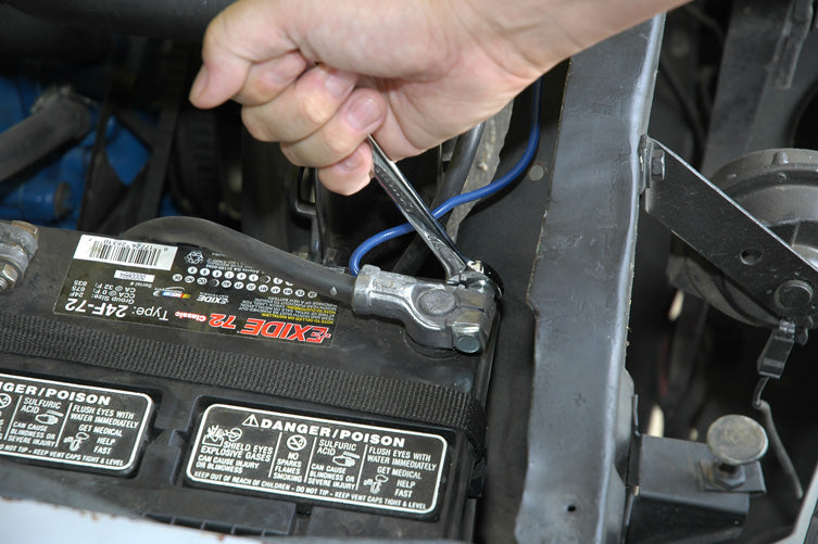

Set the cable aside so that it is out of the way. We will be connecting the MSD box to the battery later, so be sure to disconnect both cables.
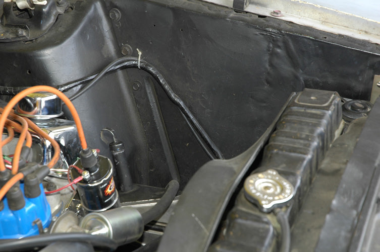
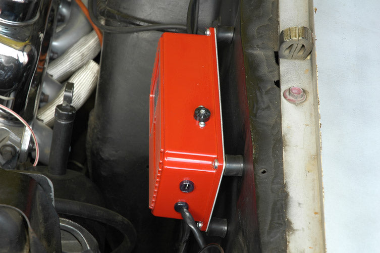
The first thing to do after disconnecting the cable is to decide on a location where you would like to mount the MSD box. The box can be mounted anywhere, although a more remote location such is in the interior of the car will require you to splice and solder more wire into the harness provided, a fairly easy task. Many vintage GM musclecars have a nice spot to mount the box on the passenger side of the firewall, while Fords offer a nice location on the fender well next to the washer fluid reservoir. As you can see by this photo of my mounting location, the sheet metal is a little less than perfect, due to a movable Ol’ Paint coming into contact with an immovable fixed object, courtesy of the previous owner. Fortunately, the 6AL box comes with rubber mounts that actually hold the box about ½ inch off of the mounting surface, so irregularities in the mounting surface can be easily overcome.

Since the panel that I am mounting the MSD box to will be replaced when Ol’ Paint becomes “New Paint”, I am not too fussy with perfection in the mounting. To locate the first hole to drill in the panel, you can simply use a metal punch or screwdriver to scribe the location. If you want the MSD box to be perfectly level, you can drill the first hole and then install the first screw loosely while scribing the second hole, using a carpenters level. As long as Ol’ Paint remains Ol’ Paint, I will not be so fussy.

Another method to scribe the 4 holes that will need to be drilled can be to make a paper template with the box on your workbench, as shown here. Punch holes in the paper after you have marked all 4 with a pen or pencil, and then scribe the mounting location on your car. Either way will work. If you are concerned about the box being perfectly level, measure twice before you drill. Nobody wants extra holes in their firewall.

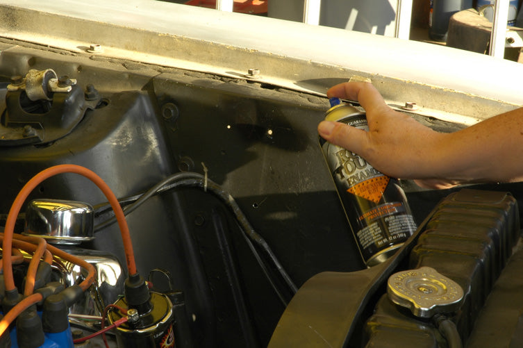
Carefully drill the holes in your mounting location. Make sure there is nothing on the other side that you can damage with the drill bit when it goes through.
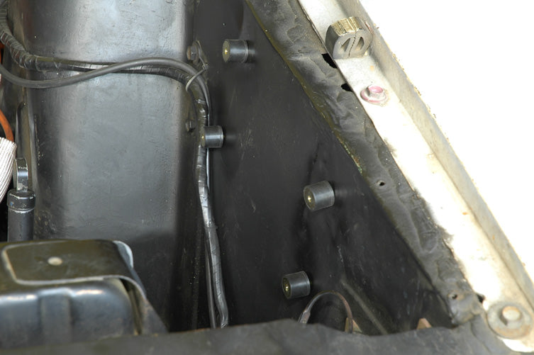
After drilling all four holes, loosely mount the 4 rubber grommets to the mounting location. It is important not to fully tighten them yet, as imperfect mounting surfaces like mine will make alignment with the box itself very difficult.

Position the box in place and install all 4 screws into the previously mounted rubber grommets. Once you have all the screws started, you can now tighten all screws and bolts, as bolt alignment is now assured.
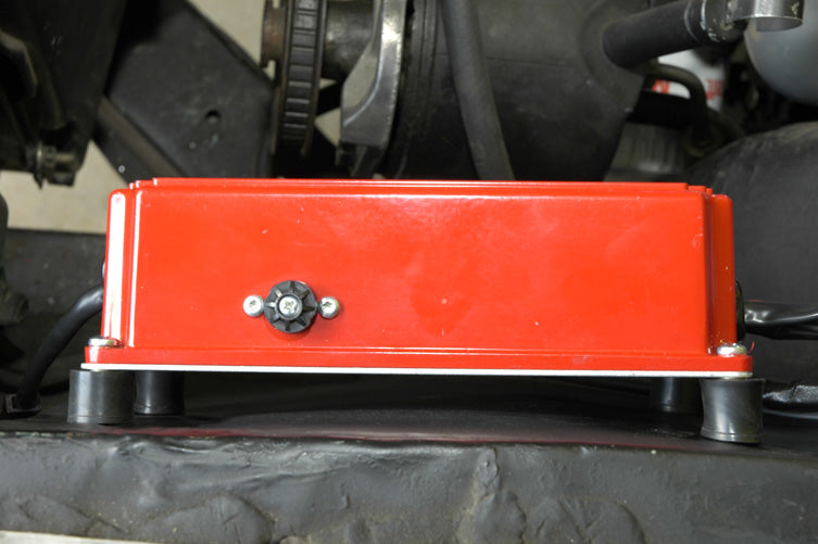
Here is a view of the mounted box from above. As you can see, the mounting location is not entirely flat. The rubber grommets do a great job of making mounting location irregularities irrelevant, and they also help in air circulation around the box, helping to keep the box cool.
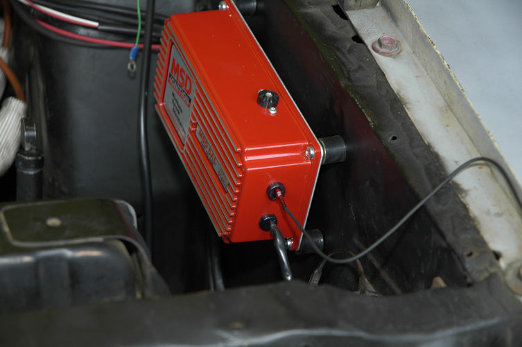
This view of the mounted box reveals two wiring connections. The top slot is the tach output terminal, for those running a tachometer, and the Magnetic Pickup Connector harness at the bottom is for those running an MSD distributor or crank trigger, factory or aftermarket magnetic pickups. Since I will be using my Pertronix Ignitor as a trigger, which is wired just like factory points, I will not need to use this harness. If you have any doubts about wiring an MSD 6AL into your system, you can simply download a PDF of the complete installation instructions, which includes simple wiring diagrams for all the most common systems, including points and/or Pertronix Ignitors.
People are often very surprised that you can still use a points style system with an MSD CD box. Since the box handles all the voltages, it simply uses the points as a trigger. Since high voltages no longer travel across the points, a CD box actually greatly increases the life of the points. The only caveat with points is their ability to mechanically keep up at very high RPM, but for daily driver use, points can work great with the MSD box.
The first wiring task I will tackle is connecting the tachometer. MSD provides a wire as part of the set, so simply plug it in to the box as shown here. Some tachometers need an adaptor to work properly with the box, and there is a handy Tachometer Compatibility List in the instructions that come with the box. It would be a good idea to download the PDF ahead of time so that you can order any necessary adaptors at the same time that you order the box.
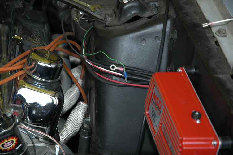
The other end of the tach connector is the black wire that you see with the eyelet, and the tach wire to my AutoMeter tach is the green wire, which also has an eyelet, as it used to be connected to the coil. As with any electrical component installation, you will usually run into situations like this. I am going to clip off both eyelets and solder a permanent connection with shrink tubing for protection from the elements. While the MSD installation kit offers various quick connect connectors for this, I prefer to make many of my connections as permanent as possible, and properly soldering and connecting wires is actually fairly simple, as this next sequence will illustrate. To do this you will need a good wire stripper/cutter, and a decent soldering iron or pencil, as well as some solder and shrink tubing. All are available at hardware, home and auto parts stores.

The first step is to clip off the eyelets of the two wires that will be soldered together. I have already clipped the green wire and the black wire is shown here.
Before twisting the two wires together, be sure not to forget to slide a piece of shrink tubing over one of the wires. You can’t get the tubing on once the wires are connected, so don’t forget.
After clipping the two ends off the wires and installing the shrink tubing, strip a small section of insulation off the end of each wire, allowing just enough bare wire for you to twist the bare ends of each wire together. After twisting them together, get the wires hot with the soldering gun and apply the solder.
This is what a freshly soldered connection looks like. The solder will melt into the wires and create an excellent connection.
Let the connection cool a little bit and slide the installed piece of shrink tubing over the freshly soldered connection.
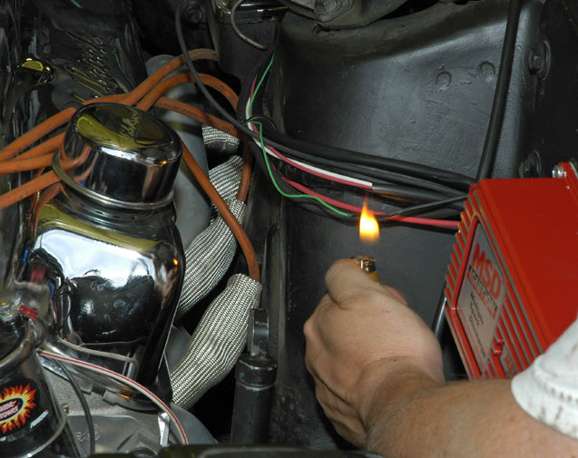
After you have placed the shrink tubing over the fresh connection, light a match or disposable lighter under the shrink tubing. You will now see why it is called shrink tubing, as the tubing contracts over the connection, making a simple and cheap weatherproof seal. Shrink tubing works much better than electrical tape, and is less likely to be adversely effected by harsh, under hood conditions. I make the majority of my direct wiring connections this way, especially connections that I don’t anticipate disconnecting any time in the near future. For connections that are frequently undone and reconnected, quick connector or spade terminal connection will probably work a little better. The connections I made from the MSD box direct to the battery were also made the same way, as I had to add length to the wires to get them to reach.
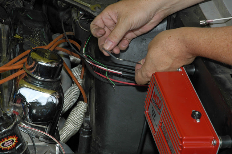
Now it is time to connect the box to the distributor and coil. There are a number of wires coming out of the wiring harness connected to the MSD box. One small harness has the orange and black wires. These will be the wires going to the coil. The other small harness has the small gauge red and white wires, and there are two heavy gauge red and black wires coming directly from the box. The heavy gauge wires will be the ones going to the battery, so we will get to those later.
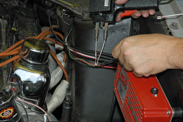
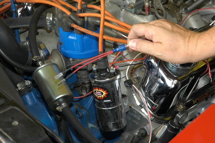
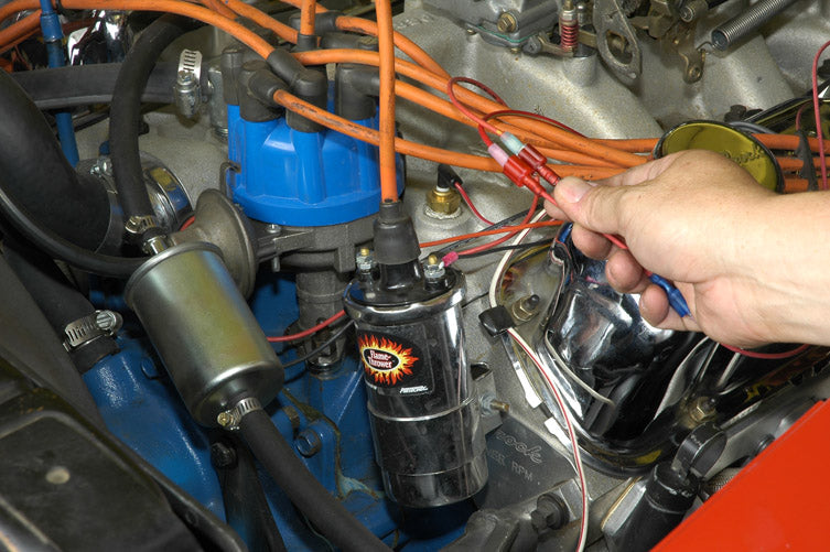
The first set of wires that we will address is the red and white wires that will be connecting to the distributor, and in my case, the Pertronix ignition trigger. Shown here is a two into one connector provided in the install kit. The small red wire coming from the MSD box will be connecting to the red wire coming from the Pertronix Ignitor in the distributor, and the red wire will also have to connect to the ignition feed wire that used to run to the coil from the ignition switch. This is the resisted 8-9 volt wire I referred to in the introduction. This handy connector will allow me to easily connect the two factory wires to the one red MSD wire. I have already attached the connector to the MSD red wire, as shown.
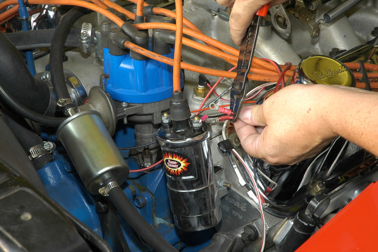
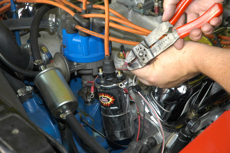
Since the factory wires originally connected to the coil, they had eyelets on them. Since I will be connecting these wires to the connector shown in the previous photo, I will need to convert these to spade terminals. Here I am cutting off the eyelets so that I can attach the spade terminals.
Here I have crimped two spade terminals that I had in stock from a simple terminal set from the home improvement store. You can get these in large assortment kits inexpensively and they are always handy to have around for projects like this one, aftermarket gauges, and car stereos. Buy them ahead of time so you don’t have to run to the store during your install.
Here are the connected spade terminals. Make sure the terminals are fully covered, so that a live wire can’t come into contact with ground, shorting your components. I decided to go with this type of connecter to allow for easy disconnect should I have a component failure in the future, like the Pertronix unit failing.
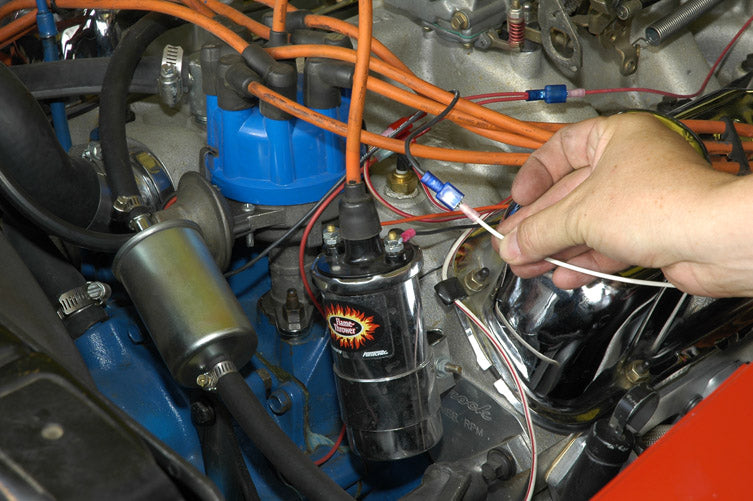
I have done the same thing with the white wire from the MSD box, connecting it to the black wire from the Pertronix unit. This is a simple one wire to one wire connection. Now the distributor is connected, it’s time to hook up the coil.
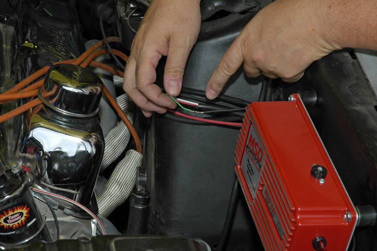
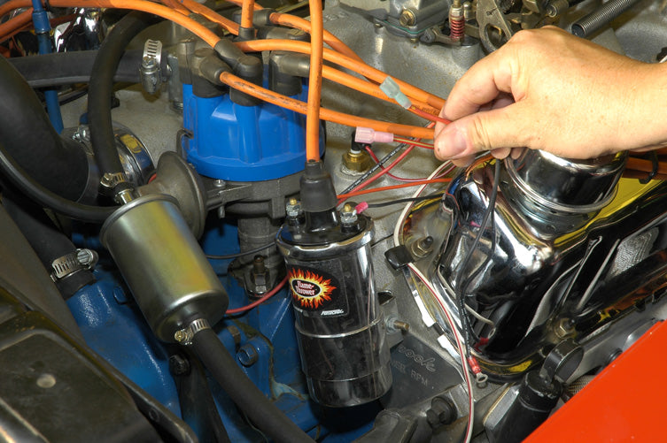
The orange and black wires from the second mini-harness from the MSD box are the wires that you will be connecting to the coil. These are the ONLY wires that will be connected to the coil. The MSD wiring harness comes equipped with spade terminals, which with the provided adaptors, can be connected directly to the coil without modification. I tend to prefer eyelets for my coil connections, as they are more difficult to pull off the coil when working on other things. They also provide a more direct connection, so I am going to cut off the spade terminals and switch over to eyelets. I am also going to switch over to the MSD Blaster coil, as it is better suited to the MSD system. The Pertronix coil internally has 1.5 ohms resistance, which is required for certain systems. The MSD coil has less resistance, which is perfect for the MSD 6AL system.
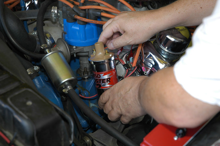
With the new coil in place, attach the orange wire to the positive terminal of the coil, and the clack wire to the negative terminal.
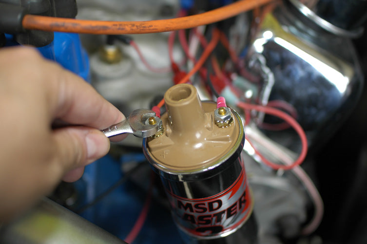
Gently tighten the nuts in place on the coil. Be careful not to over tighten, as many a good coil has been thrown away due to stripped threads on the coil posts. I will get to those ugly plug wires in a minute. We still need to connect the heavy gauge red and black wires from the MSD box to the battery before we can proceed any further.
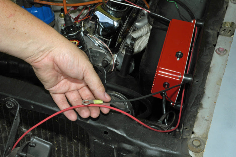
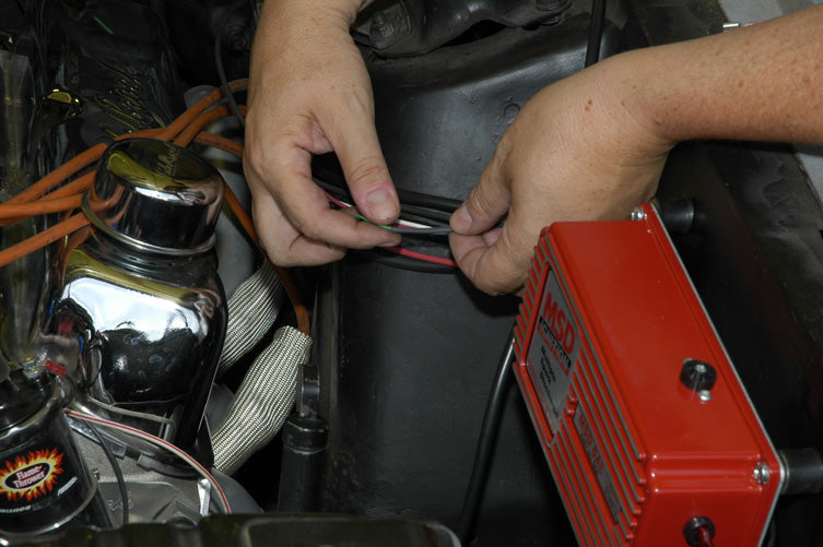
Here are the leads that will be going to the battery terminals. The factory supplied leads will not be long enough for my application, as I plan to hide the wires on the backside of the radiator core support. That means I will have to splice in an extension to get the wires to reach the battery. I will use the same method as I did when soldering the tach wire.
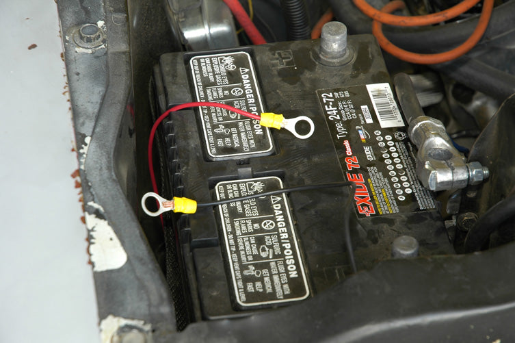
Here are the wires after splicing, measured to fit so that there is no extra wire around the battery tray area.
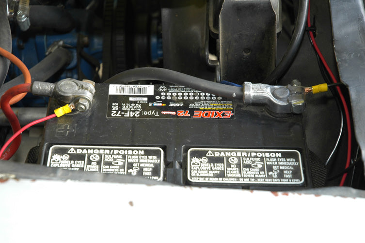
And here are the wires connected directly to the battery. Now to the plug wire replacement, and to re-gap the plugs to the recommendations provided in the MSD directions.
The next step for me, and this is optional, of course, is to re-gap the spark plugs to a wider gap setting, to take full advantage of all that extra spark. This will aid in more complete combustion, and will help take full advantage of all the benefits that the 6AL provides. I use plug wire boot protectors, as you can see here, as the clearances are rather tight in this application. These are very handy if you think that your plug wires will come into contact at any point with your headers.
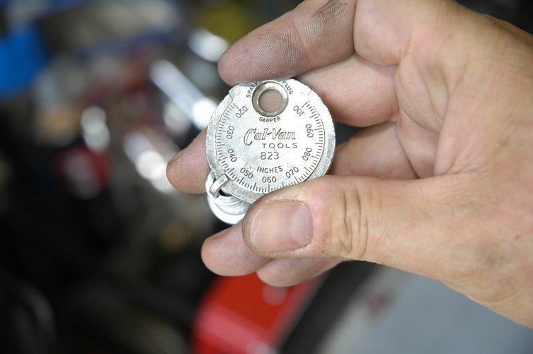
I set my plug gap to .045, which is slightly conservative for a 10.5:1 compression engine. This will be a good starting point, and I can experiment with different gaps later.
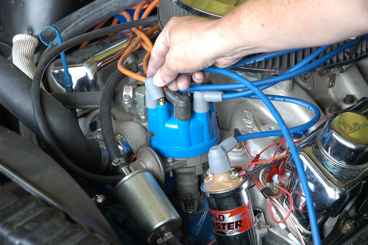
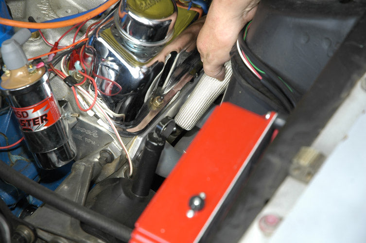
And now for the final task, installing the new MSD Heli-Core spark plug wires. Not only will these wires make my engine bay look a lot nicer, they will prevent crossfire, provide a nice hot spark, and provide good radio static suppression.
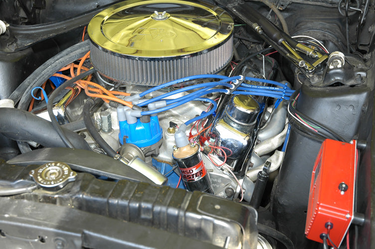
And here is the completed look. I will get some decorative wire wrap to clean up the look in the coil area as time allows.
Conclusion
Initial start-up after this install was instant. I noticed immediately that the car was much more willing to idle on cold start-up. Before the MSD install, I had to feather the throttle a bit for a few minutes to get the car to the point where I could put it in gear and go. Now the car idles on it’s own right away.
Throttle response is also instant. Around town drivability is much improved. I haven’t put the car on a dyno yet, but seat-of-the-pants feel indicates that I have gained some horsepower. Also, I used to have a slight surge while cruising at freeway speeds when lifting off the throttle, or on very light acceleration, which I could live with, but it was annoying. With the installation of this box, that problem went away as well.
Now I can go to other parts of the fine-tuning process knowing that my ignition system is state of the art, and more than capable of handling any further performance mods I throw at it. That’s a good feeling to have, and I highly recommend this system for anybody running a modified street vehicle or street/strip weekend machine.
This tech tip is from the full book, HIGH-PERFORMANCE IGNITION SYSTEMS.
For a comprehensive guide on this entire subject you can visit this link: LEARN MORE ABOUT THIS BOOK HERE
SHARE THIS ARTICLE: Please feel free to share this post on Facebook Groups or Forums/Blogs you read. You can use the social sharing buttons to the left, or copy and paste the website link: https://www.cartechbooks.com/blogs/techtips/hp-ignition-vacuum